Hi
Agree but my question is a different one and much more basic. My question is about point to point wiring - i.e.the physical implementation once the optimum components have been determined. It is a general question about point-to-point wiring but I am using the snubber as an example.
As an example: Mark has provided a very interesting tool for figuring out the appropriate components for a CRC snubber. I have my transformer, I've used Quasimodo to optimise the value of the snubber resistor, I've soldered the appropriate resistor and second cap together, and now have everything laid out on the table before me with my chosen wire for point to point wiring. I need to connect (a) the first cap across the secondaries and (b) the second cap and resistor (in series) across the secondaries. Do I need to place short pieces of wire to space (b) from (a)?
Cheers
Steve
The R+C snubber is wired across the secondary winding.
The rectifier is also wired across the secondary winding.
The snubber is effectively in parallel with the rectifier as seen from the transformer.
The snubber is effectively in parallel with the secondary as seen from the rectifier.
The snubber is very effectively shared between the rectifier and the secondary winding in that both see the snubber.
The snubber thus interacts with the L & the C, to dissipate the oscillation energy.
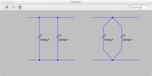
Ok I think I am struggling to get my very basic question across. An easier example: two capacitors in parallel. Look at the below as physical wiring (rather than a schematic - I just used LTSpice to draw because it was faster). Is there a difference between these two physical wirings?
Or to use my earlier example:
An externally hosted image should be here but it was not working when we last tested it.
Or to use my earlier example:
An externally hosted image should be here but it was not working when we last tested it.
Attachments
Last edited:

Ok I think I am struggling to get my very basic question across. An easier example: two capacitors in parallel. Look at the below as physical wiring (rather than a schematic - I just used LTSpice to draw because it was faster). Is there a difference between these two physical wirings?
An externally hosted image should be here but it was not working when we last tested it.
Or to use my earlier example:
An externally hosted image should be here but it was not working when we last tested it.
Is there a difference... no. Why ? Because LTSpice has "perfect" conductors. Built for real and they are different because there is resistance and inductance of the wiring and print to consider.
Remember I mentioned earlier about seeing for real with a scope what any problems are. That is the only way to approach correcting a problem. Mains born spikes and noise that appear across a secondary winding can be very difficult to irradicate and they interact with the wiring too. That is why I said there would be many opinions about how to go about the problem
") Mine is that you have to measure the problem and solution to see if it works.
Mine is that you have to measure the problem and solution to see if it works.Is there a difference... no. Why ? Because LTSpice has "perfect" conductors. Built for real and they are different because there is resistance and inductance of the wiring and print to consider.
Look at the below as physical wiring (rather than a schematic - I just used LTSpice to draw because it was faster).
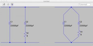
Forget about LTspice. I used it to sketch only. An alternative sketch is provided below.
I have my transformer, I've used Quasimodo (with a scope) to optimise the value of the snubber resistor, I've soldered the appropriate resistor and second cap together, and now have everything laid out on the table before me with my chosen wire for point to point wiring. I need to connect (a) the first cap across the secondaries and (b) the second cap and resistor (in series) across the secondaries. Do I need to place short pieces of wire to space (b) from (a)?
These are small parts. I'm not constrained by a circuit board. I can wire them as either A or B below.
An externally hosted image should be here but it was not working when we last tested it.
A has 4 solder joints and 6 pieces of wire. B has two solder joints and 4 pieces of wire. In A, the wires I have marked in red can be short or long. As they get shorter, A approaches B. Where physically possible, would one wire as B? Or would one take the time to solder the intervening wires (marked in red)?
(It is probable that the physical implementation with point to point wire will have resistance and inductance that differs from the Quasimodo circuit board that was used to optimise the resistor. It is possible that had one not used Quasimodo but instead went through the more laborious process with the actual wiring that one would have arrived at a slightly different resistor value. My presumption is that this isn't a grave concern as otherwise developing a tool such as Quasimodo would be a waste of time. I'm therefore not concerned about the impact of this on the optimal value of R.)
The extension of this question would be to ask, were it the case that B is preferable, if soldering the entire B "concoction" directly to the rectifier pins would also be preferable. In this case, however, one hits physical considerations because the diode pins to which the secondaries attach are further apart than the pins of Cap 1 can reach, thereby necessitating some wiring in any event. It would, however, be easy for Cap 2 + R to reach across these though. So would one in that case place Cap 1 across the secondaries at some convenient junction point (or extend the pins with short wiring and wire across the diodes) and place Cap 2 + R across the secondaries where they (after Cap 1) meet the diodes? Mark did as much here because Cap 1 was already part of the circuit and the diode leads provided a good platform for Cap 2 + R.
I'm merely trying to plan how to physically wire this all. I have my rectifier diodes in a grid, I've worked out those 4 components need to be wired and I've got my transformer in place. The diode pins would probably support Cap 2 + R. Or I could rig a platform for the entire snubber just before the diode grid, either wiring it as A or B above. Are there any guidelines as to what is preferable?
I suspect that there is little practical difference between them so long as the components are well supported but this is what I am wanting to check.
Hopefully this makes sense.
I guess the only problem" I am trying to solve is "what is 'good practice' point to point wiring?" If the only difference between these options is the resistance and inductance of the wiring, my presumption is that wherever possible one should minimise wire runs. Physical constraints dictate most things, e.g. the size of the large 22k uF caps and the size of the diodes. When it comes to fitting the snubber parts it seems there are several options. I was wondering if there were guidelines as to cleanest, best practice.
With rapid transients (where the rise time is fast) and with RF interference and oscillation, good practice doesn't always mean what you might think. I'll give you one extreme example. Take an old analogue TV and aerial system. You would think that applying a shorting link from coax lead inner to outer would remove all the signal. It doesn't. On some channels in the band the signal amplitude increases dramatically, on others it falls. Thats an extreme and perhaps not very relevant example but what I'm trying to say is that the cleanest supply might not result from what you think is the best way of wiring it all up if any spike or interference happen to fall within a "band" where your particular layout renders the filter ineffective.
Lets be practical... with an RC snubber on each diode and an RC filter across the secondary you are 98% sure to cover most issues. Also the ca values you are showing are applicable to the reservoir caps (22000uf) rather than snubbers and filters which are normall in the 0.1uf region)
Lets be practical... with an RC snubber on each diode and an RC filter across the secondary you are 98% sure to cover most issues. Also the ca values you are showing are applicable to the reservoir caps (22000uf) rather than snubbers and filters which are normall in the 0.1uf region)
Correct re capacitor values. What I mean is that the sheer size of a 22,000 uF capacitor requires that two in parallel be installed with connective wire - wiring the respective pairs of pins together directly isn't practical. The snubber components - a 0.01uF capacitor, a 0.15uF capacitor and a resistor are small enough to provide for different options (spaced, pins connected directly, on separate platform, over the two diodes where the secondaries attach to the diode bridge etc). As with most things in life, there are many ways to skin a cat but some are considered more practical, more elegant, more effective and more efficient than others.
Last edited:
I thought we were talking all snubbers (post #78)
22000uf reservoir caps... you don't add any series resistor to those. Because the charging currents are so large (tens of amps) with 22k caps I would wire both separately back to the rectifiers. It would also do no harm to add a 0.1 + resistor across the rails as well as the large caps.
22000uf reservoir caps... you don't add any series resistor to those. Because the charging currents are so large (tens of amps) with 22k caps I would wire both separately back to the rectifiers. It would also do no harm to add a 0.1 + resistor across the rails as well as the large caps.
I'm talking generally about point-to-point wiring.
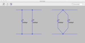
So in your diagram post #83 I would go for the one on the right to minimise interaction of the charge current of the caps.
Thanks a lot. I'm still trying to understand how the configuration on the right "minimises interaction of the charge current of the caps."
For now I have left space to insert the snubber ahead of the rectifier diode grid. I will likely just mount the caps and resistor on a lid of a small box and wire it into the gap.
Here's a pic of where I am so far. Don't laugh! My soldering skills need a lot of practice. All the joints are "good" but I have problems with insulation melt with the short runs of wire. (I'm using Kimber Kable Kwik-16 removed from it's jacket.) It doesn't look at all professional. Any tips here appreciated. (I was using a tip temp controllable solder station at 320C.)
While I redid everything, the large caps and regulator have been wired in this configuration before (with the 18V brick input) and all worked fine. (It would be good to have a better, tidier solution for the 3 cable runs from the output cap.)
I've still got to wire the fuse in and complete the wiring of the IEC inlet.
I've gone over everything a few times and I'm pretty sure I've got all the wiring of the rectifier and transformer right. That said, I have to admit to being damn nervous about plugging it in for the first time!
An externally hosted image should be here but it was not working when we last tested it.
Thanks Andrew. Easier said than done with this Kimber Kable - it's thick and very rigid. I guess from rectifier to the caps I could get a couple of turns in. The short segments across the caps and down to/up from the regulator would be extremely challenging. I could probably get a couple of twists into the secondaries from the transformer to the point where I have anchored them to the chassis. Between and the rectifier will eventually be the snubber and so the connections will again be very short and difficult to twist.
Any tips re the soldering? Hotter and work faster or some other strategy? (At the moment is looks awful!)
Any tips re the soldering? Hotter and work faster or some other strategy? (At the moment is looks awful!)
If the Kimber is that hard to work with then dump it.
Insulated 1mm diameter solid core copper is easy to twist.
I have even used hook up wire, insulated 0.6mm diameter, for PSU wiring. The added resistance helps with attenuation of mains interference.
If very high continuous currents are passing then star quad (2 cores in each direction) 0.6mm has a current rating of 1.7A. That gets you into 50W ClassA territory.
Copper is copper, you don't need any better !
- Status
- This old topic is closed. If you want to reopen this topic, contact a moderator using the "Report Post" button.
- Home
- Amplifiers
- Power Supplies
- Help a novice steadily build a linear 12V power supply?