thomaseliot said:The star ground shown is for one set (ps+amp) of boards only. What for the second set? Another star point on the second PS board then the two points connected?
While waiting I'm getting fun designing the amp front:
for other channel- another star point without connecting to other channel's star point
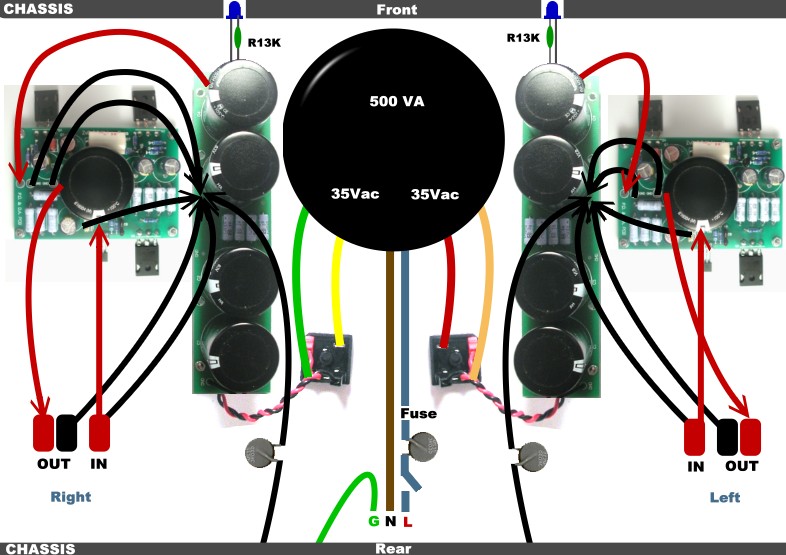
Output wiring
While wiring a doubt raised on output + and - wires.
On the amp board, output pads are labeled GND and -OUT. The -OUT is in series with C1 minus leg.
As I understand it
-OUT => Speaker +
GND => Speaker -
In Neil's schematics wire are inverted, so I wonder if I missed something.
While wiring a doubt raised on output + and - wires.
On the amp board, output pads are labeled GND and -OUT. The -OUT is in series with C1 minus leg.
As I understand it
-OUT => Speaker +
GND => Speaker -
In Neil's schematics wire are inverted, so I wonder if I missed something.
thomaseliot said:Hi Neil,
Nice idea yours of "visual schematics". I had fun with my copy.
The doubt on output wiring is because there must be a post by Nelson Pass on the subject, containing something to remember....
Maybe sombody remembers")
output cap + is in circuit ..........on muucho voltage potential
output cap - is on output side,where just 8 ohms (usually) separate it from gnd potential
Zen Mod said:output cap + is in circuit ..........on muucho voltage potential
output cap - is on output side,where just 8 ohms (usually) separate it from gnd potential
So the answer is that the negative side of the output cap C1 must be connected to speaker + through "-OUT" pad?
thomaseliot said:
So the answer is that the negative side of the output cap C1 must be connected to speaker + through "-OUT" pad?
yup
I was reading thomaseliots last post:
Then I "cooked" the amp for an hour to fix the voltage trhough the pot P1 when heatsinks are hot: nice trial if you don't have a multimeter with small clips like Steen. I found that R18 (the side toward center of the board) and R7 (toward the edge) are good sites where to anchor ordinary "crocodiles".
My question is this:
1. What is the role of the P1 pot?
2. How does one adjust it i.e. Is thomaseliots method correct.
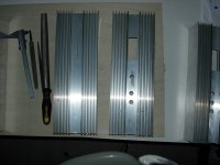
I have been gnawing away at the chassis, working on them when i have time. I have atatched a preliminary image of the heatsink with some rough holes cut for posts and sockets. Still much work to be done but there may be an end it sight.
I will post images as i get further along and no doubt more questions
Thanks
again
Then I "cooked" the amp for an hour to fix the voltage trhough the pot P1 when heatsinks are hot: nice trial if you don't have a multimeter with small clips like Steen. I found that R18 (the side toward center of the board) and R7 (toward the edge) are good sites where to anchor ordinary "crocodiles".
My question is this:
1. What is the role of the P1 pot?
2. How does one adjust it i.e. Is thomaseliots method correct.
I have been gnawing away at the chassis, working on them when i have time. I have atatched a preliminary image of the heatsink with some rough holes cut for posts and sockets. Still much work to be done but there may be an end it sight.
I will post images as i get further along and no doubt more questions
Thanks
again
Attachments
Insulating Mosfets???
I had read in antoher post that the Mosfets need to be insualted from their respective heatsinks otherwist there would be a shorting problem.
The mosfets I have used have a metal back, do i need to electrixcally isolate these from the heatsinks or can i attach them directly with a threaded screw and some thermal grease?
If they do need to be electrically isolated, what product should i use?
Hi!
I just finished my ZEN V9!
(long story short, it used to be Zen V8, but now it has become V9...)
There is one thing that I did differently. Input and feedback resistors. I used 1 K for the input and 4,7K for a feedback. (instead of 10k and 47K).
Anything wrong with that? May I leave it like that or you prefer the original values?
(Apart from low input impedance, but since I'm using a BOz to drive it, shouldn't be an issue)
Second, I used 20K pot for P1. (instead of 25K one). However, in order to get half the supply voltage at the drain of Q2, it has to be turned to max value..
What value does your P1 have when tuned properly?
Thanks,
Vix
Vix said:There is one thing that I did differently. Input and feedback resistors. I used 1 K for the input and 4,7K for a feedback. (instead of 10k and 47K).
Anything wrong with that? May I leave it like that or you prefer the original values?
Second, I used 20K pot for P1. (instead of 25K one). However, in order to get half the supply voltage at the drain of Q2, it has to be turned to max value..
Lower feedback resistors values will give you wider bandwidth
and lower distortion at high frequencies (by about a factor of
one octave). The 10K values is chosen becuase audiophile
whine and complain about input impedances. Myself, I care
naught for such concerns - simply see to it that the source
can supply the appropriate current.
Less than 1 mA... Scary, Huh?

Vaues that P1 arrive at depend mostly on the JFET, and the
values can wander over a fairly wide range. Not to worry as
long as you can get the output DC to 1/2 the supply.
Nelson Pass said:Less than 1 mA... Scary, Huh?
That little?
I might be able to put those electrons on my hand and count how many they are . . .
- Status
- This old topic is closed. If you want to reopen this topic, contact a moderator using the "Report Post" button.
- Home
- Amplifiers
- Pass Labs
- Help a noob build a ZV9