does EC output stage equate to common emitter?
whereas EF equates to emitter follower or common collector?
Hello Andrew
EC is error correction.
Regards
Arthur
Hello
I have posted an amp using Alexander front end with a modification thanks to Edmond and it shows an amp that achieves 3ppm at 80Vpp into 8ohms .
Hi Arthur,
Congratulations with this result. Still, there is one hurdle left: the clamp.
I can now see why Edmond says EC output stages are obsolete
Regards
Arthur
As a matter of fact, this is not an Alexander front end, rather a lookalike. More precisely, it is a NDFL input stage in disguise. So I would say the EC-OPS AND the Alexander-FE are obsolete.
")
Cheers,
E.
Hi Wahab,
You might think that the VAS also benefits from the additional loop gain, as the loop includes the VAS as well. Although the latter is true, the distortion of the VAS is NOT reduced, that is, due to increased loop gain (it is only slightly reduced due to unloading of the VAS output). The reason is that in both cases, ordinary Miller vs TMC, the Miller cap sees (almost) the same voltage, hence the loop gain around the VAS stays the same.
E.
Hi Edmond,
Do you agree that we can consider TMC as some
nested feedback loops, one kept from the VAS output
and the other from the OPS output , with both being
closed in the VAS input via a capacitance. ?..
In this respect, we can assume that the intercept point
of the two networks occur at high frequency , about 1 mhz ,
since at this frequency, the resistor going to OPS OP
and the cpacitance going to VAS OP have about the same
impedance.
Above this frequency , VAS OP network has lower impedance,
so the compensation converge to a conventionnal miller
compensation.
Below , this is the OPS OP network that dominate, thus, negative
feedback ratio around the OPS increase while still enclosing
the VAS, of course, since this latter provide the necessary gain
to make those feedback loops working.
Attached is a THD simulation with the tests circuits schematics.
THD of a single symetrical VAS is simulated along
with the THD of the VAS + an OPS, open loop in both case.
Then TMC is implemented in the VAS + OPS configuration.
We can see clearly that the THD doesn t increase a lot
when an OPS is added to the VAS...
With TMC implemented, the VAS + OPS THD is lower than the
one of the VAS alone, that is, TMC reduce distorsion of
both stages..
cheers,
W
Attachments
Amp with brute force clamp
Hello Edmond
Here is the amp with a what you would call a brute force clamp. This clamp still has some not so clean edges on a clipped sine wave into 2 ohms . This is my first attempt at a clamp I will attempt to improve it any feedback would be appreciated.
I am sure there is a better solution that eliminate this previous edge problem I mention and I that you can't underestimate the importance of a good clamp as can be seen by the trouble you go to with your clamps and the performance you get Edmond .
With regards to the the front end I was aware that the front end opamp had a capacitor around its inverting input and output which is why this complete amplifier has such huge gain at the low frequencies.
Regards
Arthur
Attachments
Hi Edmond,
Do you agree that we can consider TMC as some nested feedback loops, one kept from the VAS output and the other from the OPS output , with both being closed in the VAS input via a capacitance. ?..
Hi Wahab,
Agreed.
In this respect, we can assume that the intercept point of the two networks occur at high frequency, about 1 MHz, since at this frequency, the resistor going to OPS OP and the capacitance going to VAS OP have about the same impedance.
Agreed. BTW, the transition frequency is determined by R11*C7 (courtesy of Andy_C), not R11*(C4+C7) (as erroneously stated by me a few years ago).
Above this frequency, VAS OP network has lower impedance, so the compensation converge to a conventional miller compensation.
Agreed.
Below , this is the OPS OP network that dominate, thus, negative feedback ratio around the OPS increase while still enclosing the VAS, of course, since this latter provide the necessary gain to make those feedback loops working.
Agreed.
Attached is a THD simulation with the tests circuits schematics. THD of a single symmetrical VAS is simulated along with the THD of the VAS + an OPS, open loop in both case. Then TMC is implemented in the VAS + OPS configuration. We can see clearly that the THD doesn't increase a lot when an OPS is added to the VAS...
So far so good.
With TMC implemented, the VAS + OPS THD is lower than the one of the VAS alone, that is, TMC reduce distortion of both stages..
cheers,
W
Hmm... Now things get really interesting. We not only have different opinions, but we also get different results. To shed more light on this, I also have to simulate your circuits (just to make sure we are talking about the same thing). Of course this will take some time. I'll be back ASAP.
Cheers,
E.
Hello Edmond
Here is the amp with a what you would call a brute force clamp. This clamp still has some not so clean edges on a clipped sine wave into 2 ohms . This is my first attempt at a clamp I will attempt to improve it any feedback would be appreciated.
I am sure there is a better solution that eliminate this previous edge problem I mention and I that you can't underestimate the importance of a good clamp as can be seen by the trouble you go to with your clamps and the performance you get Edmond .
With regards to the the front end I was aware that the front end opamp had a capacitor around its inverting input and output which is why this complete amplifier has such huge gain at the low frequencies.
Regards
Arthur
Hi Arthur,
So you're not the only one who gets headache from that pesky clamp. Have you also tried an active clamp (or if you like a NFB clamp)? Something based on the principles as shown here: http://www.diyaudio.com/forums/soli...erview-negative-feedback-279.html#post1801149
As for compensation, you have replaced the Miller compensation (as shown here: http://www.diyaudio.com/forums/soli...erview-negative-feedback-277.html#post1776548 ) by shunt compensation (C2). Why? For improved stability or lower distortion?
Cheers,
E.
As for compensation, you have replaced the Miller compensation (as shown here: http://www.diyaudio.com/forums/soli...erview-negative-feedback-277.html#post1776548 ) by shunt compensation (C2). Why? For improved stability or lower distortion?
Cheers,
E.
Hello Edmond
Thankyou for your advice.
First thing the compensation , are you saying that C3 and C4 (both 100pf) can be eliminated (removed) by modifying the value of C2 ( 620pf) in the diagram you give a link to.
Regards
Arthur
Hi Wahab,
>With TMC implemented, the VAS + OPS THD is lower than the one of the VAS alone, that is, TMC reduce distortion of both stages..
I've just simmed your circuit (though with slightly different models) and guess what?
TMC does increase the distortion! Needless to say that I'm really puzzled.
OTOH, if I set R8 and the input voltage 100 times higher, then THD20k is roughly the same in both cases.
I'll be back Monday.
Cheers,
E.
Hello Edmond
Thankyou for your advice.
First thing the compensation , are you saying that C3 and C4 (both 100pf) can be eliminated (removed) by modifying the value of C2 ( 620pf) in the diagram you give a link to.
Regards
Arthur
Hi Arthur,
No. Certainly not! You will need all of them, i.e. Miller compensation (or equivalent) plus that 620pF cap. You can find the correct values by observing the step response, which should be critically damped (no overshoot neither 'undershoot').
Cheers,
E.
Hi Arthur,
No. Certainly not! You will need all of them, i.e. Miller compensation (or equivalent) plus that 620pF cap. You can find the correct values by observing the step response, which should be critically damped (no overshoot neither 'undershoot').
Cheers,
E.
Hello Edmond
I find that 47-100pf to ground is the value to get good transient response. In your circuit which has mosfet outputs the 100pf caps can be tied between the q3 and q4 and the output , I cant do this without a small oscillation developing.
If you look at my circuit the miller compensation is applied across different nodes, I cannot do it like you did.
Regards
Arthur
NFD clamp
Hello Edmond
I played around with your NFB clamp but I am not sure if it is optimum , I would like your opinion.
I have not included the second part of the NFD clamp which connects to the feedback.
My recovery from a clipped waveform is not as clean as some of your implementation , and am wondering if it can be further improved.
Regards
Arthur
Attachments
clamp
Hi Arthur,
>I have not included the second part of the NFD clamp which connects to the feedback.
The second part is essential. In order to make such clamp stable (in fact another NFB loop), you probably have to insert a lead-lag compensation as well. You not only have to tame the VAS (in this case the current mirrors) but also the gain stage in front of it (the op-amp). In other words, every stage, in particular when it has been compensated by means of a capacitor, needs some form of clamp. See also the 'nested clamp' of the PGP amp: PGP Amplifier (at the bottom of that page).
BTW, why you call it an "Alexander" amp. Your (and mine) is definitely different:
The Alexander amp is a CFB one, of which the closed loop gain is determined by R5, R7 & R8 (in his schematic).
Although your amp is also a CFB one (with a voltage gain determined by R5 & R8), it is preceded by separate VFB gain stage with its own frequency compensation and its own and separate FB resistor network, R6 & R7 (that determines the overall close loop gain). In this respect it is more a Bryston or special variant of Cherry's NDFL amp.
Functionally, it has nothing to do with a Alexander topology. Not every amplifier with an op-amp in the front-end should be attributed to the honorable Mr Alexander.
Cheers,
E.
Hi Edmond,
[snip]
With TMC implemented, the VAS + OPS THD is lower than the one of the VAS alone, that is, TMC reduce distortion of both stages..
cheers,
W
Hi Wahab,
In the meantime I figured out what was wrong with my previous sims: because of open loop conditions, the output voltage were different. IOW, I was comparing apples with oranges.
Making Vout equal for both cases (by adjusting the input voltage), I got more meaningful results. I've also replaced the OPS by a VCVS (gain=1) to make sure that the VAS is the only thing that creates distortion.
With Miller compensation THD20k = 425ppm and with TMC 428ppm, i.e. practically the same distortion. So my conclusion is that TMC does NOT lower the VAS distortion.
Next question: why we got different results???
Cheers,
E.
PS: I simmed the THD after 100 cycles
Hi Wahab,
Making Vout equal for both cases (by adjusting the input voltage), I got more meaningful results.
I've also replaced the OPS by a VCVS (gain=1) to make sure that the VAS is the only thing that creates distortion.
With Miller compensation THD20k = 425ppm and with TMC 428ppm, i.e. practically the same distortion. So my conclusion is that TMC does NOT lower the VAS distortion.
Next question: why we got different results???
Cheers,
E.
PS: I simmed the THD after 100 cycles
Hi, Edmond
I also adjusted the input signal such that we measure
the same output level in the sims i already posted.
You had noticed that the OPS are unloaded.
Loading the OPS, THD in the open loop variant
increase dramatically, while the gain collapse,
which is expected.
Then implementing TMC , THD decrease to levels
that are below the single VAS schematic THD..
Using more cycles in sims didn t change the picture.
Of course, the simulators calculate THD using
complexe values, i.e, using the harmonics amplitude and
phase values.
So while Harmonics can have higher amplitude in a
said sim, complex computation can give lower
ratios due to a different phase response in respect
of the harmonics.
I m to make some other tests, as now, i m
unable to give a logical answer to your questions.
cheers,
w
DC drift
Hi Wahab,
> Using more cycles in sims didn't change the picture.
Hmm....
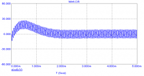
In my sim it took some time before the DC level got stable, see pic.
If the DC component is still drifting, I get a totally erroneous THD figure. If taken from the 1st cycle for example, THD20k = 18%, instead of 425ppm when taken from a stable cycle.
Apparently, you have tackled this problem in a different way.
Cheers,
E.
Hi Wahab,
> Using more cycles in sims didn't change the picture.
Hmm....
In my sim it took some time before the DC level got stable, see pic.
If the DC component is still drifting, I get a totally erroneous THD figure. If taken from the 1st cycle for example, THD20k = 18%, instead of 425ppm when taken from a stable cycle.
Apparently, you have tackled this problem in a different way.
Cheers,
E.
Attachments
2xamp
Hello Edmond
Here is the 2XAMP(new name) following your comments, attached is also the clipping performance into 2ohms (a real challenge in my opinion) as can be seen the recovery from a clipped 20KHz sine wave is very good. It does not look like it needs any additional lead compensation from the simulation.
The active clamp you designed is excellent and it makes me want to use it everywhere , not all clamps are created equal and congratulations again.
May I ask you do you think this amp can be improved further with respect to its THD performance, or does the complexity increase dramatically. Not that I think the 2XAMP performance is bad its excellent for its complexity , but any improvement is of interest.
Regards
Arthur
Attachments
Clamp
Hi Arthur,
What about calling it the 'Phoenix'.
Indeed, the waveform looks very neat. Nevertheless I would recommend also to investigate the clipping behavior under lots of other conditions: different loads, voltages, frequencies, even 100kHz.
Furthermore, I also would sim the loop response of the clamp and check the phase margin. You never know, the devil is in the detail.
Thank you!
For such a relative simple amp the performance is already amazingly good. Probably not much 'room' for further improvements, that is, without adding complexity. But a few details might need a bit more attention: PSU filtering of the front-end for better PSRR. Also bootstrapping the diodes D1 and D2, as shown in my example. Did you check THD figures with and without these diodes? BTW, what is that 1pF cap doing there?
Cheers,
E.
Hello Edmond
Here is the 2XAMP(new name) following your comments,
Hi Arthur,
What about calling it the 'Phoenix'.
attached is also the clipping performance into 2ohms (a real challenge in my opinion) as can be seen the recovery from a clipped 20KHz sine wave is very good. It does not look like it needs any additional lead compensation from the simulation.
Indeed, the waveform looks very neat. Nevertheless I would recommend also to investigate the clipping behavior under lots of other conditions: different loads, voltages, frequencies, even 100kHz.
Furthermore, I also would sim the loop response of the clamp and check the phase margin. You never know, the devil is in the detail.
The active clamp you designed is excellent and it makes me want to use it everywhere , not all clamps are created equal and congratulations again.
Thank you!
May I ask you do you think this amp can be improved further with respect to its THD performance, or does the complexity increase dramatically. Not that I think the 2XAMP performance is bad its excellent for its complexity, but any improvement is of interest.
Regards
Arthur
For such a relative simple amp the performance is already amazingly good. Probably not much 'room' for further improvements, that is, without adding complexity. But a few details might need a bit more attention: PSU filtering of the front-end for better PSRR. Also bootstrapping the diodes D1 and D2, as shown in my example. Did you check THD figures with and without these diodes? BTW, what is that 1pF cap doing there?
Cheers,
E.
- Status
- This old topic is closed. If you want to reopen this topic, contact a moderator using the "Report Post" button.
- Home
- Amplifiers
- Solid State
- HEEEELLLPPP : M. Randy Slone Mirror Image Topology Construction - Troubles