Have you also replaced the output transistors?
If so, did the output transistors get hot?
Have you checked for shorted driver transistors near the output transistors?
Did you check/replace the 10 ohm resistor between the collector of the PNP power supply driver transistor and ground?
With your meter set to ohms and the black lead on the RCA shield, do you read anything near 0 ohms if you touch the red lead to the emitter resistors (large resistors near the output transistors)? If the meter begins near 0 ohms and climbs from there, that's normal.

To prevent confusion, use the term outputs when referring to the audio output transistors only.
The term FETs would be OK when referring to the power supply transistors (the ones on the sink).
3.9v should be OK. That should be equal to ~8v of peak drive voltage. That said, I'd expect it to be higher. What is the voltage on collector of the MPSA06 power supply driver transistor?
What's the voltage on leg 1 of the L7815 regulator standing near the power supply drive circuit?
With the drive voltage you have (assuming that it's pulsed DC and not straight DC), the drive circuit appears to be OK. A short circuit or a defect in the audio circuit on the secondary side of the power supply would cause excessive current draw. Generally, a defect in the audio section of the amp would make the audio output transistors get hot but in your case it didn't.
I asked about the short from the shield to the emitter resistors because it would show if you had a shorted rail cap or a shorted rectifier.
The power supply has to be up and running for the voltage to appear on pin 1 of the L7815. If the supply was operating, there may be a problem with the rectifiers for the auxilary power supply. They are next to the power supply FETs on the heatsink (one on each side).
If you have 3.5v on the gates of the FETs, the driver IC (494) is probably OK.
Did you power up the amp with the output transistors out of the circuit to see if it would blow the fuse?
If you have 3.5v on the gates of the FETs, the driver IC (494) is probably OK.
Did you power up the amp with the output transistors out of the circuit to see if it would blow the fuse?
Which are the rectifiers? The only trans. I have that attach to the heat sink ( except for the rectifiers on the bottom) are the outputs and the fets. Is there something I can unhook instead of removing all of the outputs?
I cant even put the Fets in the supply. They instantly get hot and if I leave the power on ( without the fuse) they will blow.
I cant even put the Fets in the supply. They instantly get hot and if I leave the power on ( without the fuse) they will blow.
There is one rectifier on each side of the sink. This one is marked U1620R. Yours may be a different number. There shouldn't be an FET in that location.
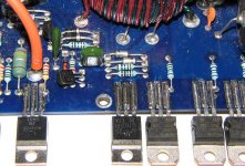
Is this board layout the same as yours?
If you have a good soldering iron, you can have all of the outputs off of the board in less than 2 minutes. Apply extra solder and lay your iron across all 3 legs at once. When the solder melts, wipe the transistor off of the pads. After the transistors are removed, clean between pads so there is no short.
Although it may cause the amp to go into protect, pulling one leg of each of the emitter resistors should stop the excessive current flow if the excessive current flow is in the amplifier section.
With either option, you only need to do it for the channel that failed.
Attachments
Can you send me a photo of that area of your board?
babin_perry@yahoo.com
The L7815 has to receive voltage generated by the power supply. The amp has relatively low rail voltage so it's possible that they use that to feed the regulator. I don't have any information on the 250. Generally the equivalent non-hcca board is close enough but that may not be the case in this instance.
If you didn't read a direct short from the emitter resistors to the shield and the outputs are out of the circuit, the problem is almost certainly in the power supply drive circuit or a shorted transformer.
Do any of the wires on the transformer look like they have overheated (darkened, flaking insulation...)?
What make/model meter are you using?
I don't think the audio drivers can cause excessive current draw with the output transistors removed.
Do any of the wires on the transformer look like they have overheated (darkened, flaking insulation...)?
What make/model meter are you using?
I don't think the audio drivers can cause excessive current draw with the output transistors removed.
- Status
- This old topic is closed. If you want to reopen this topic, contact a moderator using the "Report Post" button.
- Home
- General Interest
- Car Audio
- hcca 250