Re: I want to try your output stage!
With only 5 volts you won't be able to use JFETs, because these need a few volts of headroom. You will need BJTs which have a much lower saturation voltage. Rudolf says they sound better, too.
You choose here. Be careful if it is peak-to-peak or not. Do not saturate your current sources... I would use 1k.
I won't calculate these for you ! As you will use BJT current sources, it is easy to calculate the resistances. Will you use LEDs for biasing ?
I use 5 mA current in the lower sink, and about 12 m1 in the upper source. This gives 7 mA in my output resistor, so an idle voltage of 7 volte. You should use a lesser current to ease battery life, but your current should still be 2x the DAC output current.
Say 4 mA for the current sink on V-, and 6 mA for the current source on V+. Thus 2 mA flow in your 2K resistor, making the output idle voltage sit at 2V. If the DAC outputs +/- 1 mA, you'll get an output voltage between 1 and 3 volts, which should be fine with your transistors.
If the DAC outputs +/- 0.5 mA, use 5mA and a 2K resistor for same results.
Yes... I use 1k / 4.7 nF. The cutoff is above 20k not to get too much audible rolloff.
Have fun !
Oli said:Peufeu,
If you read the 'Simple I-V stage' thread you will find I have been enquiring about discrete I-V conversion that will operate at +/- 5 (five) Volts with my AD1865N-K. I would really like to try as many methods as possible and the final schematic on your website looks ideal for my purposes.
With only 5 volts you won't be able to use JFETs, because these need a few volts of headroom. You will need BJTs which have a much lower saturation voltage. Rudolf says they sound better, too.
I intend to set R1 at 3K. Since the Ad1865N-K outputs 1mA, this will provide me with a nice 3V signal.
You choose here. Be careful if it is peak-to-peak or not. Do not saturate your current sources... I would use 1k.
What values of resistor would seem appropriate for R2 and R3?
I won't calculate these for you ! As you will use BJT current sources, it is easy to calculate the resistances. Will you use LEDs for biasing ?
I use 5 mA current in the lower sink, and about 12 m1 in the upper source. This gives 7 mA in my output resistor, so an idle voltage of 7 volte. You should use a lesser current to ease battery life, but your current should still be 2x the DAC output current.
Say 4 mA for the current sink on V-, and 6 mA for the current source on V+. Thus 2 mA flow in your 2K resistor, making the output idle voltage sit at 2V. If the DAC outputs +/- 1 mA, you'll get an output voltage between 1 and 3 volts, which should be fine with your transistors.
If the DAC outputs +/- 0.5 mA, use 5mA and a 2K resistor for same results.
Finally, how can I calculate C1 for a given cutoff frequency?
(f=1/(2xpixRxC)?
Yes... I use 1k / 4.7 nF. The cutoff is above 20k not to get too much audible rolloff.
Have fun !
You may want to look into filters like
this.
If you're simulating have a look at group delay in the upper octaves.
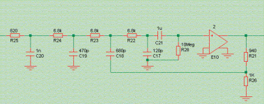
Note that R25/C20 are part of the passive IV of this particular DAC, and that
C21/R28 are arbitrary and not meant to be realistic values.
Overall gain is 6dB, implemented by the ideal voltage-controlled voltage source E10.
this.
If you're simulating have a look at group delay in the upper octaves.
Note that R25/C20 are part of the passive IV of this particular DAC, and that
C21/R28 are arbitrary and not meant to be realistic values.
Overall gain is 6dB, implemented by the ideal voltage-controlled voltage source E10.
Attachments
Steps
Hi Jan,
The steps are caused by the LATCH.
From the AD1865 datasheet:
The falling edge of LL and LR cause the last 18 bits which were clocked into the Serial Registers to be shifted into the DAC, thereby updating the DAC outputs.
LL= Latch Left
LR= Latch Right
In the Philips jargon Latch is called Wordsync (WS)
With a inverting opamp for IV-converson like OPA604 the steps are pretty sharp.
A unfiltered 3150 Hz tone looks like a sine wave with a staircase upon it! Quite harsh!
I was thinking you knew this
Steps are also present at the output of a digital filtered DAC but the frequency is much higher (8x), for a 8x oversampled DAC
janneman said:Question to Rudolf Broer:
Rudolf,
I'm thinking (still) about this. Tell me, what is the typical rise time of the steps coming out of the DAC? I mean, normally this is (digitally) filtered, no?
Gratefull for your enlightenment.
Jan Didden
Hi Jan,
The steps are caused by the LATCH.
From the AD1865 datasheet:
The falling edge of LL and LR cause the last 18 bits which were clocked into the Serial Registers to be shifted into the DAC, thereby updating the DAC outputs.
LL= Latch Left
LR= Latch Right
In the Philips jargon Latch is called Wordsync (WS)
With a inverting opamp for IV-converson like OPA604 the steps are pretty sharp.
A unfiltered 3150 Hz tone looks like a sine wave with a staircase upon it! Quite harsh!
I was thinking you knew this
Steps are also present at the output of a digital filtered DAC but the frequency is much higher (8x), for a 8x oversampled DAC
janneman said:what is the typical rise time of the steps coming out of the DAC?
I'd guess something in the range 1-10 ns, independent of the use of digital filtering.
I have just seen the truth of my I-V conversion problem
Peufeu, Elso, Tschrama et al...
Thanks for all your recent ideas about I-V conversion. Peufeu is correct that I have made a mistake- typical CD line output is 2V RMS i.e. 5.66V p-p. This is obtainable with a +/-5 (five) Volt supply opamp, but not with dicrete CCS type cicuits.
I wonder if there is any way I could buffer and amplify the output of such citcuits to a more substantial voltage output, whilst remaining true to discrete (and simple) circuitry. I know that only a small signal is required to get a reasonable sound level, but I prefer to keep the signal level high through as much of the audio chain as possible to maintain the signal to noise ratio. Perhaps opamps are the only route if I wish to keep +/-5V supplies.
BTW, Out of interest what would be the minimum rail voltage to obtain a decent line level output signal of 2V RMS?
Power supply details
Very impressed with the whole dac, I'm also in the (early) stages of building mine and had a question about ur power supply arrangement.
It is obvious that the final TL431 regulators are being fed by current sources. It is the current sources, however, that make me itch my head.
Could you run me through the calculations you used. And also what purpose is the 150r resistor after the emitter follower but before the final TL431?
Sorry if these are stupid questions, but I'm still trying to learn basic electronic theory...
Some calculations on the current source (correct me if I'm wrong):
Vb = 15.6V (formed by voltage divider of 4.6K and 2K)
Ve = 15.6V - 0.6V (diode drop) = 15V
Therefore current sourced from this setup is found from voltage across 150r resistor divided by Ve. i.e. (22.25V-15V)/150=0.048A or 48mA.
Are these calculations correct? Also what role does the shunt regulator play here? What is the advantage of using the shunt regulator over a LED for example?
From this logic, the 150r resistor between the current source and the final TL431 regulator (next to the ICs) should be a power resistor, as the power dispersed will be Vdrop = 15V-5V=10V squared / 150r = 0.7W
Re: CS8412 mode for TDA1545
Basically I just put places for solder bridges with pullup resistors because I could not be sure of which mode to choose just by looking at the datasheet... so I looked on the PCB :
Pin 17 (M3) : GND
Pin 18 (M2) : +5
Pin 24 (M1) : GND
Pin 23 (M0) : +5
So that's mode 0101 (Mode 5).
mevangel said:Pierre,
nice work indeed!
Which mode did you configure for the CS8412 to work with the TDA1545?
Best regards.
Marco
Basically I just put places for solder bridges with pullup resistors because I could not be sure of which mode to choose just by looking at the datasheet... so I looked on the PCB :
Pin 17 (M3) : GND
Pin 18 (M2) : +5
Pin 24 (M1) : GND
Pin 23 (M0) : +5
So that's mode 0101 (Mode 5).
Zodiac said:Some calculations on the current source (correct me if I'm wrong):
I'll use component references from this schematic :
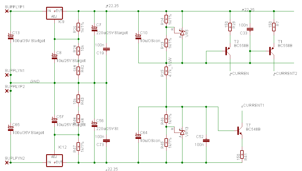
Ok, so the upper rail voltage for the current sources supply is 22.25 V from a LM317. From this we derive an emitter voltage for the current sources, using a shuntreg (VR5) set to 5V. Thus the current sources see 22.25-5 = 17.25 V on their bases.
R25, 4.7k, is only here to give bias current to the shuntreg.
This is so I can get +15V for my opamps and +5V for my digital with only one supply rail. But this raises a problem : the current sources feeding +5V circuits will dissipate a lot, hence the power resistor in the collector. It takes dissipation away from the transistors.
In my next DAC I will probably split 5V and 15V supplies in order to keep it cleaner and not make small signal transistors heat too much.
By the way, the two systems (CCS and ShuntReg) are already insulated at HF by the ferrite Choke.
And for putting a transistor on TL431 to lower impedance, why not ? I'm curious about it, have you tried, does it sound better etc ? I did not try because I had too many components already...
Regards,
Pierre
Shouldn't two stages should be well isolated anyway given the low output impedance of the transistor used in the current source? I have seen an Elso Kwak circuit without this resistor in place.
Regarding the lowering of TL431 output impedance. Do you mean using a simple emitter follower circuit?
Cheers
Regarding the lowering of TL431 output impedance. Do you mean using a simple emitter follower circuit?
Cheers
Zodiac said:Shouldn't two stages should be well isolated anyway given the low output impedance of the transistor used in the current source?
You mean high impedance, I suppose. Yes, the resistor is there primarily to dissipate heat instead of the transistor, which would otherwise overheat.
At HF, though, the ferrite bead is mandatory.
Thanks for your help! What differences would you expect if you implemented the current source with:
a) diode?
b) led?
rather than the shunt regulator...
I've already built a power supply for my tda1541 dac using a three pin regulator and shunt regs next to the supply pins on each ic, but this could be good tweaking ground!
I've also read that separating analog and digital power supplies can have a beneficial effect. i.e. running the output stage off a completely separate supply. Also some people have suggested running the Va supply for the receiver PLL off the analog supply.
What differences would you expect if you implemented the current source with:a) diode?
b) led?
rather than the shunt regulator...
I've already built a power supply for my tda1541 dac using a three pin regulator and shunt regs next to the supply pins on each ic, but this could be good tweaking ground!
I've also read that separating analog and digital power supplies can have a beneficial effect. i.e. running the output stage off a completely separate supply. Also some people have suggested running the Va supply for the receiver PLL off the analog supply.
Zodiac said:Thanks for your help!
a) diode?
b) led?
rather than the shunt regulator...
These are a bit more noisy and you don't choose the voltage. I don't know if the noise here is important though, because it is quite well rejected by the TL431 doing voltage regulation. I chose to be save and use the lowest noise option anyway.
I've already built a power supply for my tda1541 dac using a three pin regulator and shunt regs next to the supply pins on each ic, but this could be good tweaking ground!
You mean you feed your shunt regs with resistors ? In this case, yes, using current sources is easy... what about trying it and reporting here abuot what you find ?
Did you put ferrite beads on your supply lines ?
I've also read that separating analog and digital power supplies can have a beneficial effect. i.e. running the output stage off a completely separate supply. Also some people have suggested running the Va supply for the receiver PLL off the analog supply.
For the receiver PLL, I see no interest, as I reclock my signal afterwards. If you use the CS8412 PLL to extract the real clock, however...
For analog/digital supplies : with the current sources, I think they are well separated already...
Regards
Pierre
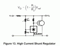
Werner said:This what I meant ...
Output-Z will be around 100mOhms
up to 10kHz or so. Cross over to an elcap with similar ESR at 5-10k, to avoid resonances.
I saw it in the datasheet... Did you try it ? It should have a lower impedance... where did you get this impedance value ?
But the datasheet mentions 150 mOhms for the TL431 alone, so is it worth to add the transistor ?
peufeu said:
But the datasheet mentions 150 mOhms for the TL431 alone, so is it worth to add the transistor ?
Supply is on my TDA1543 DAC, but no listening yet. And even so, the last time I played it with standard shunt was already weeks ago.
No, a 431's output impedance is not 150mOhms. It is more like 200m, and then only when in used in unity-gain mode. With your 1k/1k divider it is 300-500mOhm, depending on sample.
My figures are from simulations, so only indicative of course.
Werner said:No, a 431's output impedance is not 150mOhms. It is more like 200m, and then only when in used in unity-gain mode. With your 1k/1k divider it is 300-500mOhm, depending on sample.
[/B]
You're right, I forgot the feedback versus output impedance thingie.
Werner,Werner said:This what I meant ...
Output-Z will be around 100mOhms
up to 10kHz or so. Cross over to an elcap with similar ESR at 5-10k, to avoid resonances.
If you add one NPN here, you might have linear output impedance till the MHz range.
Pedja
- Status
- This old topic is closed. If you want to reopen this topic, contact a moderator using the "Report Post" button.
- Home
- Source & Line
- Digital Line Level
- Have a look at my new TDA1545 DAC (lots of details on page)