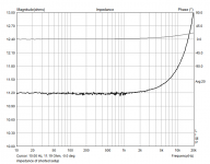
Here's what it does with the speaker leads simply shorted together. I don't know why I didn't do this in the first place, because this is what I should be trying to make work, and cannot be affected by acoustic noise. I would not be surprised if the HF rise is due to my cobbled together cable, but I am quite sure the 11.2Ω is not. Time to experiment.
Attachments
Okay, so I dissected my cable and realized I had a short on the left input jack. Dumb dumb dumb. Surely this would fix everything, I thought, but no. Well everything became much more consistent and stable, but the results are still bad.
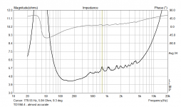
Now everything is too low. If I measure it with the speaker wire shorted, I get 0.14Ω with a small rise to 0.17 at the top end. Since the wire measures 0.14Ω with a multimeter, this seems pretty good, but something is wrong. A 470Ω resistor gives a reading of 2.89Ω. A 2.7kΩ resistor reads 16.75Ω. That's a consistent 0.6% of what I should see. Seems like a clue, but I'm not coming up with anything.
Thinking it must be the headphone output to blame, I wire up a power amp. Now my readings are really stable, but also the same as I just described.
Last edited:
Whenever I get trouble of this nature occuring it usually means I've wired something up incorrectly.
Do bare in mind that this test set-up is probably ill suited to measuring high impedances/resistances, so using 470 and 2.7k ohms is likely to give inaccurate results, but certainly not to the degree that your seeing. You can swap the left and right channel in the LIMP setup, did you try doing that and seeing if it helped? I typically get the set-up measuring really high impedances when things go wrong, rather then really low.
LIMP certainly isn't to blame mind you so you must have something wired up incorrectly or having something set-up incorrectly within the software settings of the sound card.
RE you altering the input levels of the inputs independently of one another, yes this would alter the value that the program reads as it's measuring the difference between the two inputs.
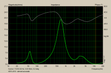
Let's see here... if I swap reference channels with the the 470Ω resistor, then I get 100Ω added to the (wrong by factor of ~0.006) result, eg. 102.89 instead of 2.89. For a 120Ω resistor, 100.64Ω instead of 0.64. If I measure a short, I get 99.86... that's odd, 100Ω minus the 0.14Ω result on the other channel. Anyway, seems pretty clear that's not the reference channel.
I have the input levels matched and calibrated now, btw.
I have the input levels matched and calibrated now, btw.
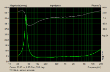
How about this? Looks pretty real. Has some ugliness, on the order of +/- 0.25Ω. I will repeat as a stepped measurement soon. edit: nevermind, the stepped measurement was identical down to the smallest details.
Attachments
Last edited:
Those ugliness could be the spider or cone. I vaguely recall that the TD15 has a phase plug? Anyway, unless you are prepared to mod the driver, that test already gives you enough idea what you got.How about this? Looks pretty real. Has some ugliness, on the order of +/- 0.25Ω. I will repeat as a stepped measurement soon. edit: nevermind, the stepped measurement was identical down to the smallest details.
My crossover is pretty much limited to 1200-1800Hz due to the dispersion I want and the lower limits of the HF part, so distortion measurements aren't going to help me much. I would be willing to try them for the sake of posting info, but I'm under the impression that valid distortion measurements are not easy to accomplish?
Anyway, I'll be back to measuring response soon, probably tomorrow, but I doubt much of anything new will be seen. I think the nearfield measurements last posted (#33) were pretty much reflection free, were they not? (I know I can't use those for crossover design though). Thanks for sticking around during my fumbling, by the way.
soongsc, yes there is a huge aluminum phase plug.
Last edited:
Valid distortion measurements are pretty easy to obtain, especially if you're not wanting to directly compare your measurements against someone elses.
Usually the loudspeaker is the part of the measurement setup that produces the most distortion, this is true even for most inexpensive condenser mics and their associated preamps.
You've already got the ability to measure the frequency response. In simple terms all you need to do is fire up STEPS, set a decent measuring level (say 2.83Vrms) and set the program running. All you have to really watch out for is clipping anywhere in the measurement setup.
Post 33 does not show a proper reflection free near field response, at least not compared to what I get when I do them. The bumps coming in at 1.5ms and 2.2ms are not driver related and are reflections from something. When doing a near field response one keeps the microphone around 1cm away from the cone and you should be able to open the gate up to 100ms without it having any real effect on the drivers high frequency response.
The impulse response from the driver alone ends at around 1ms and you can tell that parts of the driver are ringing due to the up/down zigzag shape of the decayed energy. All the dips and peaks after this are reflections coming in from somewhere.
To perform a decent farfield measurement you need to make sure that your measurement space is as free from any objects as you can make it. I mean this can be difficult but if you can manage something like the attached image it should be fairly decent.
You need to get the loudspeaker up off the floor, the higher the better, but having the centre of the driver at least 1 meter off the floor is a good starting point.
Attachments
Well, hold on now - this is back to the original issue. The 2.2ms bump shown in #33 and below is the same as what I had been calling 2.54ms (time zero is moved a little in this graph). It seems to be almost certainly driver related - the same bump shown in the other thread linked near the beginning of this thread. I had thought that the 1.5ms bump was something else, but I noticed when moving the gate out that the ripple coming in at that bump seemed to just be a lesser version of what happens when the 2.54ms is included.Post 33 does not show a proper reflection free near field response, at least not compared to what I get when I do them. The bumps coming in at 1.5ms and 2.2ms are not driver related and are reflections from something.
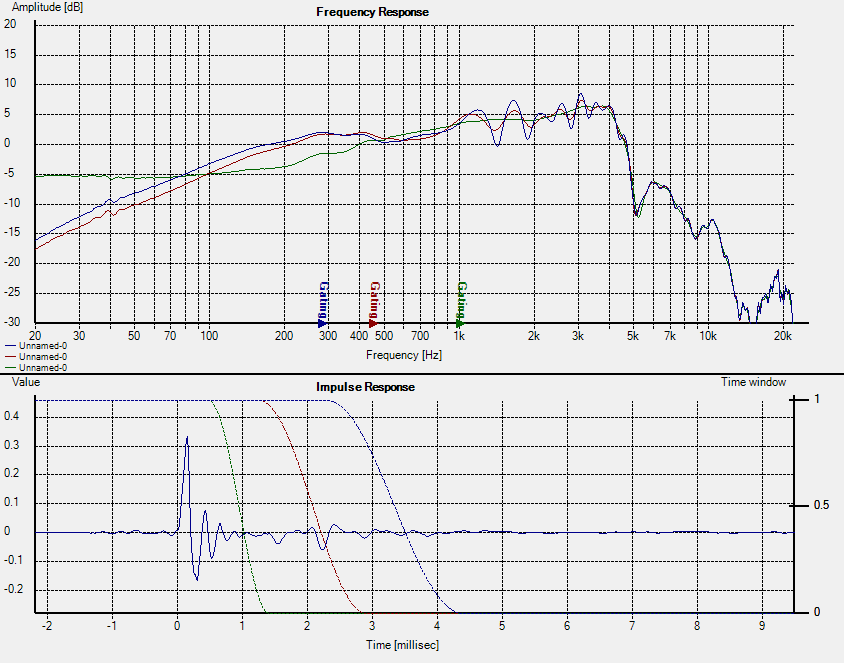
There's no way that those bumps are driver related. You can see this by examining the original impulse.
The energy is first provided to the driver and it reacts to this energy at time zero = the large positive spike. When the driver reacts to this energy the various elements within the driver are brought into action and some of them store some of this energy. Stored energy takes time to release. Now the initial positive going peak is followed by a negative going peak which is entirely normal, but for a driver with minimal ringing/stored energy action this negative going peak will be the end of it, it will decay back to zero and then flat line. In your case however some element within the driver is still releasing its stored energy and is ringing, this causes the up/down motion after the initial peak. As you can see this up/down motion is pretty much completely over by 1ms, that is the driver has released all of its stored energy.
Those peaks that come in later will be reflections coming in from somewhere, where I don't know, but you can tell that these aren't driver related by the frequency response derived from the gated impulse.
When the gate is set to 1ms this includes all of the drivers ringing and energy decay, but even with all of this included the drivers frequency response is very smooth. Now this gate is very short so only gives you accurate data down to 1khz, but nevertheless it is reflection and irregularity free.
Now as you increase the gate you are introducing some reflections into the mix and this causes the response to start becoming irregular, this is because the reflections interfere with the initial response and cause regions of varying degrees of interference to appear in the frequency response plot, in other words a form of comb filtering with the peaks and dips. You do not get comb filtering occurring unless there are two sources of energy interfering with one another,in other words the two energy source are the initial impulse and then its delayed reflections.
Last edited:
I understand why it looks like a reflection, that's why I thought it was a reflection. Do you have any explanation for how it could not be in the driver if it always appears at exactly the same time regardless of the position of the mic, the location of the speaker, the enclosure or lack of enclosure, or really anything at all? This is the question that started the thread, and I thought it was answered on page 2, but I'm certainly open to more input if you think the guys in the other thread were wrong.
It's just because time zero is set a little differently in respect to the impulse. Revisit the first two pages - everything gives the same dip at the same time. I just don't know what else I could possibly try. If you want to see something, I'll do it and post it tonight.
Don't forget, the links on page two go to someone else's measurements of what seems to be the same phenomenon with this driver, and over 13 pages of discussion about it:
(from the other thread)

Don't forget, the links on page two go to someone else's measurements of what seems to be the same phenomenon with this driver, and over 13 pages of discussion about it:
(from the other thread)
Last edited:
Do you have any explanation for how it could not be in the driver if it always appears at exactly the same time regardless of the position of the mic, the location of the speaker, the enclosure or lack of enclosure, or really anything at all?
The first peak of the impulse occurs at around 0.15ms with the first small reflection coming in at 1.6ms. This equals a path difference of around 0.5 meters. The second stronger one comes in at around 2.2ms for a path difference of 0.7 meters.
I am almost certain that these are reflections coming from somewhere, where I am not so sure. They do only occur between 1-3.5khz. The wavelength at 1khz = 34cm which is a little large for the reflections to be caused by the phase plug as it is physically too small. The same can be said for 3.5khz with a 10cm wave length, so I doubt these are being caused by the phase plug. The basket is very open and the legs are far too narrow to reflect sound at this kind of frequency. The motor structure is small enough to cause issues at 3.5khz, but not at 1khz.
In the post you've got the gates set in three different places. The first gate is set at 1ms and thus only includes the drivers initial response and then its decay. You've then got the next gate set at 2.2ms or so, this gate happens to include the first reflection at 1.6ms, but also half of the energy for the reflection at 2.2ms. Could you repeat the measurements or load the impulse response and whack a gate on it at something like 1.8ms so it only includes the first reflection at 1.6ms?
Also when performing near field measurements one doesn't need to place the microphone over the phase plug, you can do it with the microphone in front of the cone and off to the side.
- Status
- This old topic is closed. If you want to reopen this topic, contact a moderator using the "Report Post" button.
- Home
- Loudspeakers
- Multi-Way
- Has anyone here measured a TD15M? (I have them)