Interesting... what about the noise?
Zener noise is typically microvolts to a very few millivolts. This is pretty low when used in the cathode circuit of an output tube. If you use one zener per pair of output tubes the noise is common mode and cancels in the OPT.
The zener impedance for that particular diode (the 1N5350B) is specified for a test current of 100ma. I'tll be a little higher for lower bias currents, though probably not drastically so. Adding some heat sinking to the leads very near the case will help in "extreme George" situations. I wouldn't dissipate more than a watt or two in a diode like that without some heat sinking.
I wouldn't dissipate more than a watt or two in a diode like that without some heat sinking.
Yeah the 5 watt rating is a joke. With just alligator clips on the leads the diode actually starts smoking at 5 watts. They will blow at 5 watts in about 5 minutes. A zener diode fails to a short which makes life really hard on the output tubes. The diodes eat about a watt each. They don't get too hot in the amp even at full crank. They are soldered in the PC board in place of the cathode resistors. The PC board provides some heat sinking due to the large ground area.
I bought a bag full of them and matched them for Vz at 70 mA. I put one in each cathode so I could try the amp with the cathodes paralleled and without. I prefer the sound with the cathodes tied together without bypass caps. I trimmed each tube for equal idle voltage across the zener before tying them together by adjusting the screen voltage. There are 4 tubes in each channel. EL84's in PPP. Sadly the amp has been sitting on a shelf for at least a year. I blew up the screen regulator and put it aside.
I dislike dumping too much heat into the printed circuit board traces, as that can eventually result in "brown board syndrome", where the board eventually gets all brown and crispy around the mounting holes. One creative way of heat sinking axial diodes is to stick the leads through some big crimp lugs, pinch, and solder in place. The cathode lead is generally the one you worry about the most, as it will have the most solid thermal contact, though this may not be the case in axial "slug" packages.
I dislike dumping too much heat into the printed circuit board traces, as that can eventually result in "brown board syndrome", where the board eventually gets all brown and crispy around the mounting holes. One creative way of heat sinking axial diodes is to stick the leads through some big crimp lugs, pinch, and solder in place.
What I do in that cases is to attach a nut, bolt, and washers to the angles of the leads. If the hardware is made of bronze then the washers can be soldered in place to the diode leads.
What I do in that cases is to attach a nut, bolt, and washers to the angles of the leads.
I generally solder little copper flags to the leads, maybe 1/2 inch square and .040 inch thick right at the body of the part. But at less than 1 watt of dissipation they make less heat than some of the resistors on the board.
I dislike dumping too much heat into the printed circuit board traces, as that can eventually result in "brown board syndrome",
I have "brownulated" more than a few PC boards. The modern stuff handles heat fairly well. I have a test case going in my industrial amp. It was built an too small of a box with no ventillation. I am sucking 220 mA from a 150 mA Hammond sourced power transformer which heats up the whole chassis. Not to mention dissipating 40 watts in each KT88. I must admit that the shiny green resist has lost some of its shine, but it isn't brown yet and it is 5 years old.
I'm still proceeding in fits and starts on this project. I've decided that it will indeed be a "Red Light District" of sorts, as I'll be using an array of GaAsP red LEDs as cathode bias for each output stage. These are the first generation dim, deep red LEDs, which have a pretty low impedance, though not anywhere near as low as an active bias network. Ill be using an array of 8 deep by 5 wide LEDs for each side, with a couple of extra LEDs for the grid bias/balance circuit.
The front end will still be a diff pair using the 6LR8 triodes and an N-Channel depletion mode mosfet current source to set the tail current. I'll be generating the screen voltages for the output stage using an extra output tap on my SMPS. This complicates the SMPS design just a trifle, and saves a lot of parts at the amplifier end.
A schematic will follow after some breadboarding - don't hold your breath.
Well, this is the schematic I'll be breadboarding, with changes as necessary. R12 is a placeholder, and will be actually determined by the Vgs of the fet in question (Q1) at 5ma drain current.The LEDs are all antediluvian Litronix GaASP deep red LEDs (part number unknown), which have tested out so far as having really low incremental resistance at reasonable bias current. I'm interested in hearing how the Wurlitzer output iron I'm using will sound. The original transformers came from some 7868-based organ amplifiers.
Attachments
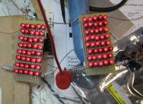
I just measured my LED of choice in the lab, for use in my cathode bias array. They are some fairly ugly Litronix red diffused parts that I can get for 5 cents apiece. The voltage drop measures like GaAsP - 1.65V at 30 mA bias. The impedance is also attractive at ~1.7 ohms. I'll use these ugly LEDs for bias and keep them under wraps, so I can save my better looking GaAsP LEDs for pilot light duty. The early GaAsP LEDs have an attractive deep red color that is unique, especially in a non-diffused package. The later, more efficient red LEDs have too much orange for my taste.
Here's the LED arrays I'll be using for cathode bias. I'm putting them under the hood, so they can be as ugly as I please. The LEDs aren't particularly bright or attractive, so it's no real loss. They do have low impedance, though. At the 30-35 ma of bias I'm intending for each tube, the bias current is 14ma/diode. That means each diode has an impedance of about 2.4 ohms, and the impedance of the total array is 2.4 X 8/5 = about 3.8 ohms - not too bad. When the amp is driven hard, the impedance of the array will actually go down.
Attachments
Please correct me if I understood it wrong, but with your setup of 5 parallel branches, for 35 mA per tube / diode array, then the individual diode current would be around 7 mA. Perhaps the diodes can withstand it and you can let only 3 branches to get to that target current. However, and depending on the slope of the impedance curve vs. current of the diodes, the total equivalent impedance for the array would be higher...
Just to let you know, at 14ma per diode, the GaAsP diodes I'm using aren't really past the "knee" of their characteristic V-I curve. It takes about 25-30ma before they start to flatten out to their ultimate low impedance. Obviously, decreasing the number of diode strings would increase the current per diode and place their quiescent bias more on the flat part of the curve. However, these are first-generation parts (well, maybe 1 1/2), and I'm concerned about the survivability when I crank the volume to 11 and really push some current through the array. The 6LR8s are vertical deflection tubes with cathodes capable of high peak current, so this is a real concern. It may be that I still have one of my ancient Litronix data books still in my stash in the basement, so it might be possible to verify the peak current capability of these diodes. However, the 5 wide array should keep the peak current down to 50ma/diode or so for fat bass pulses. This sounds reasonable. Litronix was acquired by Siemens a long time ago, and the original fab at Lawrence Expressway and Homestead in Santa Clara, California (I used to drive by it when I first relocated to Silicon Valley) was shut down ages ago. It was an EPA toxic Superfund site for a while, and now is the location of a big Kaiser medical center - go figure.
Last edited:
I've been getting creative with a square and a magic marker to discover an esthetically pleasing placement of tubes for the top of the amp, as well as for AC input module and ins/outs (on back plate). I'm using some Zenith/Sylvania 6LR8s with the tip-off on top, so the amp should look kinda cool and retro.
The amp color will be dark blue flake auto touch-up spray paint (Kragen). For pilot, what do you think? A sky blue LED (probably an obsolete SiC part), pink (?!!), aqua, or dark, dark GaAsP red? The amp might get some oak side panels if I run across some stock of about 1" thickness (possible oak sources are about a 20min drive away, but I'm lazy).
The amp color will be dark blue flake auto touch-up spray paint (Kragen). For pilot, what do you think? A sky blue LED (probably an obsolete SiC part), pink (?!!), aqua, or dark, dark GaAsP red? The amp might get some oak side panels if I run across some stock of about 1" thickness (possible oak sources are about a 20min drive away, but I'm lazy).
The amp color will be dark blue flake auto touch-up spray paint (Kragen). For pilot, what do you think? A sky blue LED (probably an obsolete SiC part), pink (?!!), aqua, or dark, dark GaAsP red? The amp might get some oak side panels if I run across some stock of about 1" thickness (possible oak sources are about a 20min drive away, but I'm lazy).
If you are going retro, then dark-dark GaAsP red. And what about a small window, the size you wish, in the front with polished-diffused sanded acrylic showing the light of the LED biasing? The diffusion would let only the red light pass through and hide the experimental build out of sight.
You could make it a rectangular slot or several of them for added effect.
I'm using some Zenith/Sylvania 6LR8s with the tip-off on top, so the amp should look kinda cool and retro.
Maybe it's my imagination but they look like what a 12AU7 wants to be when it grows up.
Maybe it's my imagination but they look like what a 12AU7 wants to be when it grows up.
Or what a 12AX7 wishes it could be, but can't in its wildest dreams (a vacuum state Walter Mitty?).
- Status
- This old topic is closed. If you want to reopen this topic, contact a moderator using the "Report Post" button.
- Home
- Amplifiers
- Tubes / Valves
- Happy New Year - A New Amp to Argue About...