The topology of differential amp/splitter into pentode outputs will remain the same.
Thats my whole pinto' contention, really. Or maybe it isn't...
If the current source and mirror are good as I believe they will be,
does it defeat the phase splitter? I mean, what signal does V2A get?
Both paths are held to 1/2 of a constant current. There is no UTurn
of folded current to couple differential signal between the cathodes.
Seems you are hoping for an averaged 1/(Mu-1) voltage coupling at
the cathodes to split the difference and follow at 1/2 input swing?
It just might... Not as familiar with pure voltage theory of operation.
Last edited:
Attached is the first schematic for another bratty push-pull amp using a pair of 6LR8 triode-pentode vertical deflection tubes per side. The 6LU8 would work just as well - same tube, different pinout. The schematic as shown has all the bell and whistles, and I'll decide how many of them I want to keep as I go on.
Options - balance control, regulated screen/not, also whether I want to use the electronic cathode bias circuit or a mess of LEDs instead (maybe Stu, just maybe). I bought the Electronic Goldmine jumbo pack of 2000 pieces of 3mm green LED (1 cent each!) so I'll be prepared if I decide to do that. I figure 5 parallel strands of 7 LEDs in series would make the nut and treat the LEDs pretty conservatively.
Since you opened this thread with the challenge for an argument...
What's the goal for this design? It will be a "one-off" with no classic sound one way or the other. With all of the SS current and voltage control you can't say it has the "tube" sound, (if there ever was really such a thing.) It's not really an experiment in using the 6LR8 in the classic tube circuit for the fun of having a "purebred" 6LR8 powered amp. All the SS stuff nullifies the attempt since the old tube amps never had all the SS regulation which would (if you believe the SS stuf has a real impact) change the distortion profile and all that goes with that ie,.feedback factor...
You should start with the pure non-SS design, measure that, then build your hybrid, measure that amp and come back with a comparison with real numbers instead of the typical nebulous HA attemps to descibe the "sound."
Since you opened this thread with the challenge for an argument...
I can't speak for the wrench man but some of us have built enough "classic all tube" amps to last a life time. I personally have been building tube amps for about 45 years. It's time to move the tube world forward. It has been said that everything that can be done with tubes has been done. This is not so when you add some modern components. There are a few people here who can simulate and calculate "hybrid" designs and a few of us who build them. 10 years ago putting a mosfet or even a silicon rectifier in a tube amp drew a lot of flak. It it wasn't for us, we would all still be connecting a 6SN7 to a 300B to a 5U4 for ever.
The 6LU8 classic amp has been done and measured. Why do it again unless you want one.
6LU8 Sweep-AMP
Work on this amp is going on in the background, as it is being multiplexed with about five or six other projects. I decided as a tip o' the hat to SY to go ahead and try LED cathode bias for the output stage, and concocted some 7 deep X 5 wide arrays using green LEDs from Electronic Goldmine (2000 for $20 - 1 cent each!). Since these are standard yellow-green GaP LEDs, they'll weigh in at about 2V each, meaning that an array 7 LEDs deep will drop about 14V, which is just where I need to be to bias the pentode section of the 6LR8.
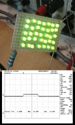
Attached is a photo of the array being hit with a current step. This was accomplised by putting the array in series with an electronic load with an internal step load feature. Quiescent current was 60mA, stepped to 150 mA. This represents a quiescent bias of 30mA/tube, then an extreme step cutting off one tube and pushing the other to 150ma. The scope picture attached shows the resulting voltage step. The overall array incremental resistance is 2.2V/90mA = 24.4 ohms. Under these conditions, each LED in the string has an incremental resistance of ~17 ohms. The LEDs are operating well within their pulsed current rating, so any decision to add more strings to the array would be based on achieving a lower incremental impedance.
The photo shows the array with a 10 ohm current sense resistor dedicated to each output tube. The array voltage shown in the scope picture was measured directly across the LEDS, not including the resistor voltage drop.
Attachments
Last edited:

I bought a big bag full of these LED's from the Goldmine when they were on sale. I'll try to remember to bring some in here tomorrow to measure their dynamic resistance. I plan on trying a bunch of them for EL84 cathode bias. So far I have found nothing that comes close to the camera phone flash chips, but I can't get any more of them either.
LITEON LTL912SEKSA "Piranha" 3.37 Lumen Red LED
LITEON LTL912SEKSA "Piranha" 3.37 Lumen Red LED
Any of the active loads that I have ginned up so far will soundly kick the LED array's butt without breaking a sweat. However, it may be that 10-20 ohms resistance is sufficient to reap the benefits of LED cathode bias. I may just put another 10 ohm resistor in parallel with the LED array and declare victory. I was guessing that the little green LEDs were about 10 ohms apiece, but large signal excitation looks different. I may try again with a smaller current excursion to see if I get different numbers. These can't be all that different from the ones SY was using in his RLD.
Any of the active loads that I have ginned up so far will soundly kick the LED array's butt
SHHHHH don't tell anyone....esperially SY, but a plain old 5 watt zener diode whups up on the LED's. I used a 1N5350B from On Semi. It is rated at 2.5 ohms zener impedance.
I just went back to my setup with a couple of good meters and sharpened the pencil a bit. For a current excursion of 60ma to 150ma (accurately measured) I get a voltage excursion from 14.49V to 16.35V, or a delta Vee of 1.86V. This puts the resistance of the array at 20.7 ohms, and the resistance of each induividual LED at ~14.8 ohms. For both green LEDs, and red leds, your mileage may vary as to resistance. I'll have a bunch of HP/Avago LEDs coming soon. I'll try a similar measurement with them, but with a single string of 7 to keep the tedium factor down. I also have a bunch of ancient Litronix GaAsP red LEDs that might be worth a shot. Those will need more LEDs per string to reach my 14V target, though.
Then again, I alrady have a couple of active cathode bias circuits built up. When presented with a similar current transient, you can't even see any voltage excursion on the o'scope. (decisions, decisions). However, I already have an amp using similar bias networks in process. This may be an opportunity to see just how stiff you need the catode bias network in order to derive some benefit.
Then again, I alrady have a couple of active cathode bias circuits built up. When presented with a similar current transient, you can't even see any voltage excursion on the o'scope. (decisions, decisions). However, I already have an amp using similar bias networks in process. This may be an opportunity to see just how stiff you need the catode bias network in order to derive some benefit.
Last edited:
If you dump some do-nothin current into them LEDs to keep em'
always on? And biased more toward the flat part of the curve...
Let the tubes cut off sure, but never the bias LED underneath.
If you insist to ride sanded curves into total cutoff, I'd suggest
square law Schottky diodes. Like glass, zero recovery glitch...
always on? And biased more toward the flat part of the curve...
Let the tubes cut off sure, but never the bias LED underneath.
If you insist to ride sanded curves into total cutoff, I'd suggest
square law Schottky diodes. Like glass, zero recovery glitch...
This may be an opportunity to see just how stiff you need the catode bias network in order to derive some benefit.
My first experiment was simple. I connected all 8 EL84 cathodes together and wired them to a 0 to 25 volt 5 amp Sorrensen linear supply. THe supply can not sink current, so I put an 8 ohm resistor across the output and set the current limit to max. I wound up with 13 volts on the supply and individual tube currents were adjusted via the screen voltage.
This worked very well and has prompted more experiments. I'm in a similar situation with too many projects, so this one is currently sleeping on a shelf.
KP
Keep in mind that we're talking about a P-P design, so there's always a lot of current through the LEDs, as both output pentodes share the LED array. With the currents I'm using, the LEDs are already pretty much into the flat part of their characteristic. I could dump the zeners I'm using for screen regulation into the array as well, but it wouldn't make a whole lot of difference.
It so happens that the Goldmine bulk LEDs (at least the green ones they're selling) are fairly resistive. They are R.G. Allen parts. If you remember R.G Allen, they never really made anything for themselves, but re-marked parts obtained from vendors like Futaba and Micron (I never found out who they got to make their electrolytic caps). Who made the LEDs is anyone's guess. The price was right, though. I'm going to try some HP green GaP and Litronix GaAsP red LEDs tomorrow to see how they measure up - a string of 7 for the HPs and a string of 9 for the Litronix.
Well, it's a real concern for an SE amp, for sure. The first solid state cathode bias I did was for a little SE amp I called the "Mighty Mite" (the thread is there for those who search), and I included an extra resistor for some current to keep the bias supply at least half-alive when the output stage was in cutoff. That one used a pair of 6LR8s. I may revisit that amp and convert it to partial feedback to eke out some more power.
Here's the data for a string of Lite-On GaP yellow-green LEDs, some HP LEDs of the same composition, and some ancient Litronix GaAsP deep red LEDS. I'll give the raw data, the incremental impedance, and the average impedance. I took 4 data points for each set, 10mA-40mA at 10mA intervals.
Liteon (7 led string) - 10.7ma/14.4V, 20.4ma/15.56V, 30.3ma/16.42V, 40.8ma/17.33V Incremental impedances - 17.08 ohms, 12.4 ohms, 12.38 ohms Average impedance - 13.9 ohms
HP (7 led string) - 10.7ma/14,28V, 20.2ma/15,27V, 30.2ma/16.13V, 40.1ma/16.98V Incremental impedances - 14.88 ohms, 12.28 ohms, 12.26 ohms Average impedance - 13.11 ohms
Litronix (8 led string) 10.7ma/12.85V, 20.2ma/13.07V, 30.4ma/13.2V, 40.3ma/13.31V Incremental impedance - 2.89 ohms, 1.71 ohms, 1.39 ohms Average impedance - 1.94 ohms Warning - I started with a 9-led string, but one slacker in the bunch decided to drop a lot of volts, so he was cut out of the string. QC was still an issue with these early LEDs.
Clearly, if you're concerned about absolute lowest impedance for an LED string, you want to find a bunch of the ancient, relatively dim deep red GaAsP leds, from the early days of LED technology. Either that, or some red LEDS with large die size. Just like SY did, you'll need to do a bit of shopping around and measurement to make your own conclusions.
I tested a few of the LITEON LTL912SEKSA diodes that I got from the Goldmine. They are rated for 70 mA and I left one cranked to 100 mA for a while without issue. They should be able to handle a reasonably overdriven amp without failure. The dynamic resistance of each LED is about 10 ohms. This is fairly linear and constant over 20 mA to 70 mA. One device:
I Vf
5 2.07
10 2.16
20 2.30
30 2.41
40 2.52
50 2.62
60 2.72
70 2.82
I Vf
5 2.07
10 2.16
20 2.30
30 2.41
40 2.52
50 2.62
60 2.72
70 2.82
Here are the incremental impedances for the Electronic Goldmine "Piranha" red led, calculated using the data that George listed in his last post. The incremental impedances give you a good idea as where the diode curve starts to flatten out. they are as follows - 18, 14, 11, 11, 10, 10, 10. This shows that the diode impedance starts to really flatten out between 20 and 30 ma. The average impedance is 12 ohms. The incremental impedance is calculated between two adjacent voltage/current points using the formula Z = (V2-V1)/(I2-I1). The average impedance uses the same formula, but instead of using adjacent voltage/current points, the voltage/current readings at lowest and highest current are used.
Its easy to set up a spreadsheet in Excel to do the calculations, and you can plot the results afterwards if you feel so inclined. You can probably do the same with the spreadsheet routine in Open Office. I haven't tried that one, though.
Its easy to set up a spreadsheet in Excel to do the calculations, and you can plot the results afterwards if you feel so inclined. You can probably do the same with the spreadsheet routine in Open Office. I haven't tried that one, though.
Last edited:
SHHHHH don't tell anyone....esperially SY, but a plain old 5 watt zener diode whups up on the LED's. I used a 1N5350B from On Semi. It is rated at 2.5 ohms zener impedance.
Interesting... what about the noise?
- Status
- This old topic is closed. If you want to reopen this topic, contact a moderator using the "Report Post" button.
- Home
- Amplifiers
- Tubes / Valves
- Happy New Year - A New Amp to Argue About...