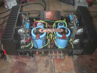
Here is one of my 220's with new 35,000 uf caps bypassed with 470 uf, 6800 ohm bleeders, and 2.2 uf caps. At the same time I replaced the RCA jacks with new modern gold plated and the Speaker jacks with same. I also put an IEC power jack in for a dedtachable cord.
At 8 ohms it does 155 watts with .007% THD. I haven't checked it at 4 ohms or in mono mode. I have a second one I am doing the same thing to and should end up with some nice monoblocks.
Chuck
At 8 ohms it does 155 watts with .007% THD. I haven't checked it at 4 ohms or in mono mode. I have a second one I am doing the same thing to and should end up with some nice monoblocks.
Chuck
Attachments
Lme49830
I did not find the datasheet of the 49830 on the web but only the 49810. I suppose they are similar in nature.
You mean using the chip, then a follower, then the L-mosfets?
Have you already tried that?
felixx said:What about to change the bjt's with a single chip LME49830?
I did not find the datasheet of the 49830 on the web but only the 49810. I suppose they are similar in nature.
You mean using the chip, then a follower, then the L-mosfets?
Have you already tried that?
Re: Lme49830
The LME49830 data sheet only became available a few weeks ago. I am still waiting for samples. You won't need a driver stage even with the IRF parts.
fab said:
I did not find the datasheet of the 49830 on the web but only the 49810. I suppose they are similar in nature.
You mean using the chip, then a follower, then the L-mosfets?
Have you already tried that?
The LME49830 data sheet only became available a few weeks ago. I am still waiting for samples. You won't need a driver stage even with the IRF parts.
You mean using the chip, then a follower, then the L-mosfets?
Indeed.
http://www.national.com/pf/LM/LME49830.html
Thoughts?
You won't need a driver stage even with the IRF parts.
On Hafler sch. was 2 pairs of mosfet's.For that topology I think the 49830 do the job easy.But I want to use 4 pairs of 2SK1058/2SJ162.
Considering these do you think there is a MUST for another driver stage?
I've run pairs of 2KS1058/J162 with the LM4702 -- to my delight -- but have not yet received the LME49830 -- will comment with actual results when I get them in -- the LM4702 can only source/sink about 5 mA, the LME49830 is 10X this.felixx said:
Indeed.
Thoughts?On Hafler sch. was 2 pairs of mosfet's.For that topology I think the 49830 do the job easy.But I want to use 4 pairs of 2SK1058/2SJ162.
Considering these do you think there is a MUST for another driver stage?
the LM4702 can only source/sink about 5 mA, the LME49830 is 10X this.
Indeed and I count on that to drive well 4 pairs.
I myself wait the samples.
Input Z and Rectification
I am modding a DH 200 (PC-6 board) and have four questions.
1) Can I replace R3 (22kOhm) with a 47 K resistor to increase the input Z (I am using a "passive pre-amp" i.e., 10K pot and would like to have a 10:1 ratio on the "output" to input Z).
Any problems? I noticed this was done with the DH 220 (PC-19 board)
2) I would like to add a thermistor for inrush protection. What is the specification on this?
I assume it is simply wired in series between the switch and the transformer. Is this correct?
3) I will be bypassing the PS caps with 47uF caps. Is there any reason to go ahead and put in larger PS caps (replacing the 10,000uF caps). What is a suggested value?
4. Without having to add heat sinks, is there a way to improve the rectification? What would be the suggested specification? Would it be wired in the same way as before?
BTW, I will be also be adding bypass caps on the input coupling caps and also a bypass cap on the 470uF electrolytic (C5)
Thanks for your collective patience,
-Tom
Tom,
Just about all your questions have been answered in previous posts in this thread, my best advice is to go back and read them.
I have printed out some of them for reference. really good reading.
Almost everything good thats a real improvement has been done on the pc19 boards.
Good reading,
Elwood
Just about all your questions have been answered in previous posts in this thread, my best advice is to go back and read them.
I have printed out some of them for reference. really good reading.
Almost everything good thats a real improvement has been done on the pc19 boards.
Good reading,
Elwood
Re: Re: Lme49830
Thanks Jackinnj and felixx !
Based on the block diagram provided it looks that the driver stage is already part of the chip. 50 ma drive current seems OK for my 3 pairs and even for my 5 pairs mosfet amps!
Slew rate is good also. But I am curious on the topology used (input, VAS, ...) in the chip? Is it diamond buffer for the driver stage?
It means a really simple pcb artwork for the front end of the mosfets then...
Do you plan to use the suggested National pcb artwork?
Thanks
jackinnj said:
The LME49830 data sheet only became available a few weeks ago. I am still waiting for samples. You won't need a driver stage even with the IRF parts.
felixx said:
Indeed.
http://www.national.com/pf/LM/LME49830.html
Thoughts?
On Hafler sch. was 2 pairs of mosfet's.For that topology I think the 49830 do the job easy.But I want to use 4 pairs of 2SK1058/2SJ162.
Considering these do you think there is a MUST for another driver stage?
Thanks Jackinnj and felixx !
Based on the block diagram provided it looks that the driver stage is already part of the chip. 50 ma drive current seems OK for my 3 pairs and even for my 5 pairs mosfet amps!
Slew rate is good also. But I am curious on the topology used (input, VAS, ...) in the chip? Is it diamond buffer for the driver stage?
It means a really simple pcb artwork for the front end of the mosfets then...
Do you plan to use the suggested National pcb artwork?
Thanks
eyoung said:Tom,
Just about all your questions have been answered in previous posts in this thread, my best advice is to go back and read them.
I have printed out some of them for reference. really good reading.
Almost everything good thats a real improvement has been done on the pc19 boards.
Good reading,
Elwood
Elwood,
Thanks for having a look. In fact I have read the previous posts (and there are many). But my specific questions have not been addressed.
re: the Input Z - there was additional components around the input and I did not know if these were also required.
re: rectification - mention was made of tackling this but no specifics were given about the part and wiring (it seemed to be part of a larger mod)
re: inrush limiter - again no specific part was mentioned - I am unfamiliar with these
re: larger PS caps - I did not see any suggested values
Thanks,
-Tom
WithTarragon said:
Elwood,
Thanks for having a look. In fact I have read the previous posts (and there are many). But my specific questions have not been addressed.
re: the Input Z - there was additional components around the input and I did not know if these were also required.
re: rectification - mention was made of tackling this but no specifics were given about the part and wiring (it seemed to be part of a larger mod)
re: inrush limiter - again no specific part was mentioned - I am unfamiliar with these
re: larger PS caps - I did not see any suggested values
Thanks,
-Tom
a) Input can be increased easily from 22k to 47k. Just change the corresponding feedback resistor from 22k to 47k too. Since the gain of the amp is determined by the ratio of the 2.2k and the 100 ohms there is no problem.
b) larger PS caps: I use 2 x 30000uf in one DH-200 and also 4 x 14000uf in another DH-200 with no problem. For the latter I use 2 rectification bridges (one for each channel).
c) "BTW, I will be also be adding bypass caps on the input coupling caps and also a bypass cap on the 470uF electrolytic (C5)":
good idea.
Tom,
You can up the filter capacitance to around a pair of 26K uF devices but they verge on the chance that switch and bridge rectifier might be damaged. If using such large capacitance you might want to look into soft start circuits.
Yes, you can put a thermistor in series with the incoming AC. Some just hang this device on the left channel thermal switch. Some question the use of a thermistor with an AB class amp as it might limit the dynamics when a lot of current is required. But, the DH-500 amp went to the use of such a device to protect its switch and bridge.
The 22k resistor cannot be changed. It must match the other 22k resistor in the feedback circuit, else a lot of DC offset will occur. There is more to determining input impedance than just on resistor.
Rectification? Rectification of what?
Dick West said:Tom,
...
The 22k resistor cannot be changed. It must match the other 22k resistor in the feedback circuit, else a lot of DC offset will occur. There is more to determining input impedance than just on resistor.
Rectification? Rectification of what?
Dick,
yes it can be changed see my previous post.
Dick West said:Fab,
I meant it can't be changed with replacement of just ONE resistor. But, as you also point out, the gain of the amp is also changed.
Cheers....
Dick,
For clarification, the gain of the amp is determined MAINLY by the ratio of the 2.2k and the 100 ohms and not the 22k (or 47k) resistor. However, a small amp gain change is due to the divider of input circuit:
22k / (22k + 2.2k) = 91% compared to 47k / (47k + 2.2k) = 95%
Also, the 2.2k is in parallel with the feedback resistor which gives an additional 5% increase if 47k is used instead of 22k.
But, it will cause no harm to the amp.
Thanks
eyoung said:Fab,
What value cap are you bypassing the electrolytics on the driver board with, I have seen the 100uf caps bypassed with .1uf
and I have seen suggestions to make the 100uf caps 220uf since the modern caps take up less space. Whats your take on that???
Elwood
Elwood,
I have no test result to justify that but 0.1 uf bypass is ok in my book for bypass as per almost every other design.
Increasing from 100uf to 200uf may help but it is really the quality of the cap that is making the difference. Since I use a regulated supply for my DH-200 amps, I have not testd the difference between 100uf and 220uf.
Thanks
But I am curious on the topology used (input, VAS, ...) in the chip? Is it diamond buffer for the driver stage?
I don't know...yet..(searching..). about the topology but if I have any news I will post.
- Home
- Amplifiers
- Solid State
- Hafler DH-200/220 Mods