Re: Re: voltage drop
Hi Fab,
I've changed the mains voltage of the amp, so everything was included. But I suppose that the part of the circuit where this voltage variation would have a greater impact is the one decoupled by R34/R28, i.e. the one that you suggest to regulate.
I agree about the benefits of regulating the power supply (of course not for the final stage, where you could probably have a reduction in dinamic range using regulated power supply), but I'm wondering about the effect of the voltage loss on the regulator (if there will be any voltage loss).
Well, about a dual mono configuration, I tend to disagree with this solution, supposed equal the total filtering capacitance. For "all left" or "all right" signals I can use double the energy in respect to the dual mono and all I loose is an some channel separation (do I really need it?).
About cascoding the VAS.... please be patient, what is a low Cob transistor?
I have read almost all the thread, some of the modifications indicated are already implemented in my amplifier (I think all the modifications that leave unchanged the boards, that, apart from having included the output mosfets on it, are the standard PC-6). I would like to see what can I modify on the boards too, in particulary I'm very interested in the memory effect solution. I'm studying the papers proposed on this thread, do you have any good suggestion?
Of course I will!
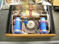
I start including a picture of my amp.
Thank you,
Paolo
Hi Fab,
fab said:
Have you tried to change ONLY the driver voltage or the voltage of both the driver and output stage?
Anyway, regardsless of the driver voltage used, lots of today's "hi-fi" power amps have a regulated voltage driver stage so the increase in parts must justify it otherwise peoples are crazy...
I've changed the mains voltage of the amp, so everything was included. But I suppose that the part of the circuit where this voltage variation would have a greater impact is the one decoupled by R34/R28, i.e. the one that you suggest to regulate.
I agree about the benefits of regulating the power supply (of course not for the final stage, where you could probably have a reduction in dinamic range using regulated power supply), but I'm wondering about the effect of the voltage loss on the regulator (if there will be any voltage loss).
-Double mono power supply (if transfo have 2 separate windings) for the output stage;
-Cascode the VAS with low Cob transistors
Why do not incorporate most or all improvements suggested im this thread?
Well, about a dual mono configuration, I tend to disagree with this solution, supposed equal the total filtering capacitance. For "all left" or "all right" signals I can use double the energy in respect to the dual mono and all I loose is an some channel separation (do I really need it?).
About cascoding the VAS.... please be patient, what is a low Cob transistor?
I have read almost all the thread, some of the modifications indicated are already implemented in my amplifier (I think all the modifications that leave unchanged the boards, that, apart from having included the output mosfets on it, are the standard PC-6). I would like to see what can I modify on the boards too, in particulary I'm very interested in the memory effect solution. I'm studying the papers proposed on this thread, do you have any good suggestion?
Good luck and keep us posted on your progress")
Of course I will!
I start including a picture of my amp.
Thank you,
Paolo
95Honda said:I still have a custom wound torroid with 2 sets of secondaries for a dual mono DH200 supply if anyone is interested... A project I started 15 years ago and never finished....
Could you please give me some more infos?
(power, regulation, $$$, etc)?
Where do you live?
Ciao
Paolo
It is a Banner Magnetics Torroid, it was specifically made for the DH200. It is moel # DH-2 and even comes with an adapter plate made to fit the holes where the originall was. I also have a set of bridges with HEXFRED diodes and a dual mono filter bank with 4x10,000 ufd caps. Cardas binding posts and Kimber RCAs. All wired with 12 awg kimber kable....
I dunno, $100 for the whole thing? It is missing the output stage and cover, but has the glass-epoxy boards....
Oh yeah, I had already made the cuts and modifications for the extra pair of output devices per channel. This was the first one I botched, it was 15 years ago, I was pretty new at this then. I was succesful at later attempts....
Hi Paolo
As said previously clipping will occur at lower voltage thus loss of a few watts. Best option is of course an additional secondary higher power supply. Effect on bias will not occur since the circuit is indenpendent of power supply voltage.
You are theoritically right but in practice most of the energy - in music signal - comes from low frequency where signal is essentially mono so the "doubling" is not really the case. NAD used to inverse the phase of left and right signal to provide "more" energy.
However, my intention for dual mono was more to double all parts of the power supply (double bridges, double capacitance).
Cob stands for collector-base capacitance of bipolar transistor. This capacitance varies dynamically with signal amplitude and must be minimize since its effect is multiplied by the gain of the transistor in a VAS. Several Video driver transistors have a Cob as low as 3pf.
I see that you are already using another chassis sicne the one of the DH-2xx is a little to small...Therefore, if you check my web site under "Double mono dual classes Power Amp 15W/8 ohms Class A - 75W/8 ohms Class B" you will see a circuit schematics based on the DH-200 topology but with a few enhancements...
Very nice construction

pidigi said:Hi Fab,
...but I'm wondering about the effect of the voltage loss on the regulator (if there will be any voltage loss).
As said previously clipping will occur at lower voltage thus loss of a few watts. Best option is of course an additional secondary higher power supply. Effect on bias will not occur since the circuit is indenpendent of power supply voltage.
pidigi said:
Well, about a dual mono configuration, I tend to disagree with this solution, supposed equal the total filtering capacitance. For "all left" or "all right" signals I can use double the energy in respect to the dual mono and all I loose is an some channel separation (do I really need it?).
You are theoritically right but in practice most of the energy - in music signal - comes from low frequency where signal is essentially mono so the "doubling" is not really the case. NAD used to inverse the phase of left and right signal to provide "more" energy.
However, my intention for dual mono was more to double all parts of the power supply (double bridges, double capacitance).
pidigi said:
About cascoding the VAS.... please be patient, what is a low Cob transistor?
Cob stands for collector-base capacitance of bipolar transistor. This capacitance varies dynamically with signal amplitude and must be minimize since its effect is multiplied by the gain of the transistor in a VAS. Several Video driver transistors have a Cob as low as 3pf.
pidigi said:
...I would like to see what can I modify on the boards too, in particulary I'm very interested in the memory effect solution. I'm studying the papers proposed on this thread, do you have any good suggestion?
I see that you are already using another chassis sicne the one of the DH-2xx is a little to small...Therefore, if you check my web site under "Double mono dual classes Power Amp 15W/8 ohms Class A - 75W/8 ohms Class B" you will see a circuit schematics based on the DH-200 topology but with a few enhancements...
pidigi said:
...
I start including a picture of my amp.
.
Very nice construction
pidigi said:
Could you please give me some more infos?
(power, regulation, $$$, etc)?
Where do you live?
Ciao
Paolo
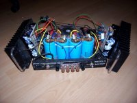
Tried answering your email, but it was returned. The answer is yes, and everything you see in the picture(s).
To bad, I was in Italy last month, in Latina Scavo for a week....
mike-tracy.edgar@hotmail.com for
email and I will set up the shipment...
fab said:Hi Paolo
As said previously clipping will occur at lower voltage thus loss of a few watts. Best option is of course an additional secondary higher power supply. Effect on bias will not occur since the circuit is indenpendent of power supply voltage.
I've measured 0.9V on R28 (47ohm) at 64V. This means that in the original configuration the input and VAS are already ~1.5V below the output stage. Theorically, using a low droop regulator, you could be in the same range.
But of course you have to dimension the regulator in order to be able to regulate in a certain range of mains voltage, say +/-10% (if the mains voltage will be even lower, but here seldom happens, you will go without regulation), so you have to design a regulator that will supply say 55V (64V-10%=57.6V). I plan on using a simple zener with a transistor to buffer the current (I really don't like 78XX and 79XX, and neither 317s), so a 56V zener - 0.6V of Vbe will be in that range.
And yes, after the test that I made, I fear that this difference will be audible. Apart for the clipping problem, why in your opinion a lower supply voltage could have caused this sonic degradation?
However we are talking about a load of 20mA, so adding few turns on a toroid will not be a problem....
You are theoritically right but in practice most of the energy - in music signal - comes from low frequency where signal is essentially mono so the "doubling" is not really the case. NAD used to inverse the phase of left and right signal to provide "more" energy.
However, my intention for dual mono was more to double all parts of the power supply (double bridges, double capacitance).
ah, ok, in this case I completely agree with you! For my installation I need 2 stereo amps (I am biamping my ML monoliths): if I will use the 2 amps in a vertical biamping, the dual mono approach will be mandatory. With an horizontal biamping, I can accept an amp with a smaller power supply for the panels, but I think I will go with the vertical biamping to reduce speakers cable lenght.
Cob stands for collector-base capacitance of bipolar transistor. This capacitance varies dynamically with signal amplitude and must be minimize since its effect is multiplied by the gain of the transistor in a VAS. Several Video driver transistors have a Cob as low as 3pf.
I see that you are already using another chassis sicne the one of the DH-2xx is a little to small...Therefore, if you check my web site under "Double mono dual classes Power Amp 15W/8 ohms Class A - 75W/8 ohms Class B" you will see a circuit schematics based on the DH-200 topology but with a few enhancements...
Thanks, Fab, I will have a look and, be prepared, I will have a lot of questions for you very soon!
Ciao
Paolo
P.S.:95Honda, I wrote you an email
pidigi said:
I plan on using a simple zener with a transistor to buffer the current
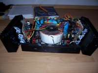
This is pretty much what I did with my DH-220. I have 60v regulated to the boards and 65 V unregulated to the outputs. I am although using a separate smaller transformer to supply 80v unregulated to the regulators. (see previous post for pictures.)
pidigi said:
I've measured 0.9V on R28 (47ohm) at 64V. This means that in the original configuration the input and VAS are already ~1.5V below the output stage. Theorically, using a low droop regulator, you could be in the same range.
But of course you have to dimension the regulator in order to be able to regulate in a certain range of mains voltage, say +/-10% (if the mains voltage will be even lower, but here seldom happens, you will go without regulation), so you have to design a regulator that will supply say 55V (64V-10%=57.6V). I plan on using a simple zener with a transistor to buffer the current (I really don't like 78XX and 79XX, and neither 317s), so a 56V zener - 0.6V of Vbe will be in that range.
And yes, after the test that I made, I fear that this difference will be audible. Apart for the clipping problem, why in your opinion a lower supply voltage could have caused this sonic degradation?
However we are talking about a load of 20mA, so adding few turns on a toroid will not be a problem....
The regulator must have a higher input voltage (several volts) to do the job properly. Also, do not forget that your main power supply voltage will reduce upon high current demands (unless you have a power supply much bigger than the original DH-2xx amp). Also, the lateral mosfets have a high RDSon so several volts are lost at high current demand in addition to the power supply voltage transient reduction. So at 5A, you loose about 5 volts in the mosfet Drain-Source plus the power supply reduction. The original DH-2xx diodes between the driver circuit and mosfets power supply help to reduce the effect of transient main power supply reduction but not for the VDS loss.
For the sonic degradation, it depends of the power at which it was tested and how much the voltage was reduced or course. Reducing the mosfet power supply voltage reduces a lot the maximum power allowable as stated above. Also, was the power available of the variac sufficient for high current demand?
But if you add a few transfo turns thus using a separate supply fro the driver I would go for at least the same voltage or higher than the mosfet power supply to get the maximum power available from the amp.
Sze said:
This is pretty much what I did with my DH-220. I have 60v regulated to the boards and 65 V unregulated to the outputs. I am although using a separate smaller transformer to supply 80v unregulated to the regulators. (see previous post for pictures.)
Hi Sze
Could you share your secondary power supply schematics and why not using a higher regulated voltage if you have 80V at input?
fab said:
Also, the lateral mosfets have a high RDSon so several volts are lost at high current demand in addition to the power supply voltage transient reduction. So at 5A, you loose about 5 volts in the mosfet Drain-Source plus the power supply reduction. The original DH-2xx diodes between the driver circuit and mosfets power supply help to reduce the effect of transient main power supply reduction but not for the VDS loss.
The RdsOn will reduce the output power of the amplifier and is not related directly to the power supply characteristics, is it? But would help if more output mosfet are paralleled? If I remeber well the Hafler 9505 has 4+4 output mosfet per channel, reaching a higher damping factor too. I'm planning to put 3+3 on the boards, but do you think that 4+4 would be another significant improvement?
For the sonic degradation, it depends of the power at which it was tested and how much the voltage was reduced or course. Reducing the mosfet power supply voltage reduces a lot the maximum power allowable as stated above. Also, was the power available of the variac sufficient for high current demand?
The variac was good, infact with a 220V output from the variac we didn't noticed any major degradation respect to the direct mains connection.
And yes, the power used was very low. So I suppose that we didn't have any clipping during the test.
The differential input pairs have a constant current sink, so they shouldn't be inluenced if there is a variation in the supply voltage. The remining part is the the VAS and the bias adjusting circuitry. But the VAS, if we remain well far from clipping, shouldn't change hi behaviour too, so only the bias change can be responsible.
But if you add a few transfo turns thus using a separate supply fro the driver I would go for at least the same voltage or higher than the mosfet power supply to get the maximum power available from the amp.
Which should be better voltage? How much over the mosfet supply voltage?
Ciao
Paolo
eyoung said:hello again...
could you not take a/c from the a/c in at the bridge rectifier ~120v and make a separate p/s board for the driver board since it pulls ~.5a or 1 amp for both driver boards, then regulate from there???
Elwood
Actually you cannot use the same voltage to obtain another psu because the share the same groud reference
Ciao
Paolo
dh200 ocillation
hello again,
i'm looking for advice or input, to make along story short i had my hafler apart bought it on ebay as is of course cleaned up afew cold solder joints did the star grounding repaced the speaker posts and rca jacks. to be safe i powered up with a variac and 60w light bulb in the mains first left channel dc offset settled out
to 30mv, then i checked current draw on left channel just about 350ma. did same on rt side dc offset a little higher about 70mv
checked current draw at about 140ma . not thinking about the light bulb as a current limiter i set rt side bias to match left side.
being overly confident i plugged the mains straight into the wall
and turned it on and instantly fried r28(pc6 board) in both channels. replaced all 4 47r resistors ck'd diodes in same circuits.
i started looking at all the resistors because they have all been replaced prior to my with the addition af a few film caps ala pc19
boards, i noticed the source resistors were all 470r but on pc19 boards 2 were 470r and 220r on the other side so i cut ot the 2 470r resistors on the 2sj49's and put in the 220r in both channels.
i put it all back together left side steady as a rock(using light bulb and variac to 120v lowered bias to below 100ma, went to left side soon as i got to 50v current draw would fluctuate from 100ma to 500ma with light bulb pulsing, i took a wild guess and replaced q9. same result i lifted the 2r2 resistor to ground from rt rca moved the pulstion to a higher voltage so i lifted left rca 2r2 to ground then both sides pulsed put left rca gound back stopped left side pulsing.
so did i upset the balance when i put the 220r source resistors in or do i have a flaky transistor in my left driver board,
any thoughts before i start putting the 470r source resistors back in. all input will be greatly appreciated.
thanks, Elwood
pidigi said:
The RdsOn will reduce the output power of the amplifier and is not related directly to the power supply characteristics, is it? But would help if more output mosfet are paralleled? If I remeber well the Hafler 9505 has 4+4 output mosfet per channel, reaching a higher damping factor too. I'm planning to put 3+3 on the boards, but do you think that 4+4 would be another significant improvement?
The variac was good, infact with a 220V output from the variac we didn't noticed any major degradation respect to the direct mains connection.
And yes, the power used was very low. So I suppose that we didn't have any clipping during the test.
The differential input pairs have a constant current sink, so they shouldn't be inluenced if there is a variation in the supply voltage. The remining part is the the VAS and the bias adjusting circuitry. But the VAS, if we remain well far from clipping, shouldn't change hi behaviour too, so only the bias change can be responsible.
Which should be better voltage? How much over the mosfet supply voltage?
Ciao
Paolo
For clarification, the maximum voltage excursion at the mosfet is :
Vpsu - ID*Rds. If ID or Rds are big than the max power is reduced. If the Vpsu is reduced at high current (loading of the transfo) then the max power is also reduced.
These lateral mosfet have only a max current of 7 amps. So more (matched) in parallel increases the dynamic current capability of the amp. If you have loudspeakers which are difficult to drive (low impedance and/or low sensitivity) than it should help. But to respond to how much improvement I really can not tell since it is depending on so many factors...
For the sonic degradation, as you say the bias of the driver circuit (not ony the diff input pair) is not dependent of the psu voltage. The VAS is biased by the collector load of the diff input which is constant current. The Vbe multiplier giving the voltage for the mosfet bias current is also independent. In fact, I really can not understand why reducing the psu voltage from a few volts can possibly alter the sound. If that would be the case than no amp less than 100W rms could be done using this topology and that is not the case...
For the driver psu voltage, it is always a compromise between power consumption and staying away from transistor saturation. However, I would not see benefit going 10V higher than mosfet psu.
Thanks
- Home
- Amplifiers
- Solid State
- Hafler DH-200/220 Mods