The scheme is ok. However the diodes should be 3 to 5W....
Any location should do to electrically ground the chassis. Ensure to have a good connection though.
Thanks
Fab
The specs for the 1N4005 at mouser do state 3W for power dissipation, did you perhaps mean 3 - 5 amps?
If so would something like a 1N5406 would be more suitable?
Thanks Again
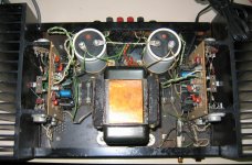
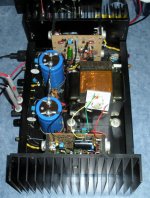
I am sure that some of the pros out there have seen worse, but I ended up with a DH200 that was just downright nasty.
It was such a mess that I didn't even want to plug it in to test it
An obvious kit build that was poorly done, wiring all over the place and it had rust everywhere, even plated components and fasteners were rusted.
It was even nastier than the picture shows, as someone had spray painted over much of the rust, including a bunch of overspray on various components and the heatsinks themselves.
I tore it right apart and replaced the nasty stuff with spare parts I had from other builds.
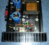
I took the bare chassis and cover over to a buddy that had a sand blasting booth, I stripped it down to bare clean metal and then primed and painted.
The heat sinks were stripped down, thoroughly washed and then cleaned with solvent, sockets reinstalled and output wiring cleaned up and soldered properly.
Installed new heat sink compound and output insulators, upgraded electrolytics & bypass film caps, metal film resistors, larger bridge rectifier, ground wiring & buss improvements, better speaker posts and rca input jacks, inrush limiter, new heavier duty switch etc.
I also have new larger power supply electrolytics, but will install them at the very end to avoid possible dripping of flux and solder on the new caps.
Although it was in pretty rough shape to start with, these old Halfers are just too nice to throw away.
It was such a mess that I didn't even want to plug it in to test it
An obvious kit build that was poorly done, wiring all over the place and it had rust everywhere, even plated components and fasteners were rusted.
It was even nastier than the picture shows, as someone had spray painted over much of the rust, including a bunch of overspray on various components and the heatsinks themselves.
I tore it right apart and replaced the nasty stuff with spare parts I had from other builds.
I took the bare chassis and cover over to a buddy that had a sand blasting booth, I stripped it down to bare clean metal and then primed and painted.
The heat sinks were stripped down, thoroughly washed and then cleaned with solvent, sockets reinstalled and output wiring cleaned up and soldered properly.
Installed new heat sink compound and output insulators, upgraded electrolytics & bypass film caps, metal film resistors, larger bridge rectifier, ground wiring & buss improvements, better speaker posts and rca input jacks, inrush limiter, new heavier duty switch etc.
I also have new larger power supply electrolytics, but will install them at the very end to avoid possible dripping of flux and solder on the new caps.
Although it was in pretty rough shape to start with, these old Halfers are just too nice to throw away.
Attachments
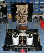
Finally got the DH200 all together and tested.
It sounds good, and is even quieter than other Halfers I have had.
Not sure if that is because of the cap/transformer ground arrangement, and hate to pull it apart to find out if that is the case.
I should be able to confirm that on the next one I rebuild.
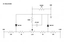
The DC Offset is 9mV on one channel, 30mV on the other, which is well within specs.
I would like to do a little better though, and add a DC Offset circuit to be able to set them both close to 0mV.
In previous posts it mentions a circuit that was in an Audio Amateur Magazine 1/83, which I have not been able to locate.
I made up a sketch of how it was described, but would like to confirm that it is correct.
It also mentions a small pp cap to help reduce noise, I would like to confirm its location as well.
I have checked on the DC Offset circuit for the DH220, and there are some noticable differences between the two, in components and values.
Also tvrgeek, you mention splitting the input and output power supplies by lifting the output side of the 68 ohm resistors, I take it that you meant the R28 & R34 47 ohm resistors on the PC6 boards.
It sounds good, and is even quieter than other Halfers I have had.
Not sure if that is because of the cap/transformer ground arrangement, and hate to pull it apart to find out if that is the case.
I should be able to confirm that on the next one I rebuild.
The DC Offset is 9mV on one channel, 30mV on the other, which is well within specs.
I would like to do a little better though, and add a DC Offset circuit to be able to set them both close to 0mV.
In previous posts it mentions a circuit that was in an Audio Amateur Magazine 1/83, which I have not been able to locate.
I made up a sketch of how it was described, but would like to confirm that it is correct.
It also mentions a small pp cap to help reduce noise, I would like to confirm its location as well.
I have checked on the DC Offset circuit for the DH220, and there are some noticable differences between the two, in components and values.
Also tvrgeek, you mention splitting the input and output power supplies by lifting the output side of the 68 ohm resistors, I take it that you meant the R28 & R34 47 ohm resistors on the PC6 boards.
Attachments
Should also mention that I found a good way to clean up rusted fasteners, brackets etc. on this Hafler rebuild. Just soak the rusted components in white vinegar for 3 days or so, and they come out looking like new. I did the same for some bolts and gate latch on my truck, and it worked great for that too. Heavier rust may require a week or 2, agitating the solution from time to time helps speed up the progress. You can wipe the metal components down with thin oil to protect it, or use metal prep and then paint it.
One of the best mods I tried is to just cascode the input stage. I did this many years ago and dont have the unit any more but I am sure someone here can do it. It makes a fairly noticable (audible) improvement in PSR and THD. If you didnt want to do a complete over-haul of the circuitry, this is easy and effective upgrade.
Just lift the Input diff pair collector(s) out of its pcb hole and solder the emitter of the cascode to the collector and then put the collector of the cascode transistor in the pcb hole. Add a bias for the cascode and you done.
Then I added film bypassing and better wiring, and more power RC filtering to the input. Not much else. On the DH500, there was room to replace the filter caps with Sangamo 101X series caps (ultra low ESL and ESR). A 600v or higher 0.1mfd PP film across the ac power switch contacts will increase the switch life.
THx-RNMarsh
Last edited:
One of the best mods I tried is to just cascode the input stage. I did this many years ago and dont have the unit any more but I am sure someone here can do it. It makes a fairly noticable (audible) improvement in PSR and THD. If you didnt want to do a complete over-haul of the circuitry, this is easy and effective upgrade.
Just lift the Input diff pair collector(s) out of its pcb hole and solder the emitter of the cascode to the collector and then put the collector of the cascode transistor in the pcb hole. Add a bias for the cascode and you done. ...
THx-RNMarsh
Cascode with CFP in input stage:
http://www.diyaudio.com/forums/solid-state/31131-hafler-dh-200-220-mods-3.html#post395669
Thanks
Fab
Thanks rsavas, providing for built in limiting at either end of the pot range makes perfect sense.
Those resistors are also included in the DH220 board design, as R5 & R6.
Does the C3 cap between the pot wiper and ground apply as well, for noise reduction?
RNMarsh and fab, the input modes are a little beyond what I wanted to do with this DH200, but definitely something I can look into for future builds. I should point out that although my build and solder skills are fairly decent because of years of hobby electronics and pro plumbing, the extent of my education in the field is only high school electronics, and 2/3 of that was tube orientated (mid 70s). I can read schematics fairly well, but don't always understand why something was done the way it was, or how to improve it.
fab, that schematic is nice and clear, although I am not sure about how the EBC connection points relate to connecting to the oem boards. I have read through the entire thread a few times, but might have to go over parts of it some more yet.
Yup, just like they did on DH-220, now that I look at it. yes the cap (C3) filters noise and makes for a smooth adjustment.
Now that I think about it some more there is no regulated supply for the front end so by rights, the dc offset ckt really should be from a regulated supply and not an unregulated supply. So make a simple +/- regulated supply for the offset adjust ckt, by using some equal value zeners and heavilly filter the zener noise using some big ecaps, 100-220uF. Should be easy enough to do, just need to calculate the R & zener power dissipations.
Haflers DH-220 method is okay to follow since they used D7,D8 as crude voltage regulators. Obviously, the best method is to have a constant current supply to the zener's, so that supply V changes do not change the zener voltage, since they are driven from a CC source or use a precision zener such as a TL431 and you can do away with the CC sources. Supposedly the Onsemi TL431 are the lowest nose of the available suppliers of this part.
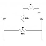
Put together a test circuit based on the DH220 design.
Had a 4.7K pot on hand, so adjusted the circuit for that.
I tried a 1 meg resistor between the pot and R3, but it was too much.
With the 100K resistor it worked fine, allowing for adjustment down to less than 1 mV.
I already have some metal film resistors on hand, just have to track down some good multi turn pots.
Attachments
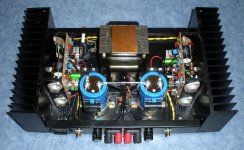
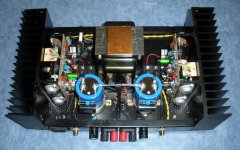
Mounted the components on perf board, into as small a size as practical, and then trimmed each board down to size.
Used some old serial port shell hardware to make a couple of small plated angle brackets.
I had to remove each C1 and its bypass caps to be able to install the boards/brackets.
I then fastened the DC Offset boards to the heat sinks, and wired them to the appropriate points.
Adjusted both channels down to less than 2 mV (including fluctuations).
Worked well, and did not have to alter or cut up the original PC6 driver boards.
Its an easy upgrade to do, the hardest part is to securely fit the boards into the available space.
The size and position of the C1 caps you go with will also need consideration.
Make sure you test fit everything before you start drilling holes and mounting stuff.
Attachments
Not to be a downer on your project, but it seems like it would be less work to just match the diff pairs. On the last DH200 I rebuilt, I was able to get each channel down to 10mVDC with just matching with a Heathkit IT-18. It didn't take many transistors to get there either.
Stormrider, I went with the way I did because I already had everything on hand, and it cost next to nothing.
If I order components from a place like Mouser, usually there is at least a 2 week shipping delay as well.
Before I added the circuits the amp was not too far off, 9 mV (right ch) and 30 mV (left ch).
I agree that matching is a great idea, it is something that I never got around to doing myself.
If you can offer any details on the procedure that would be great, I am sure others would be interested as well.
A few questions that come to mind are:
What other equipment other than the vintage Heathkit tester would do the trick?
I have had mixed luck on picking up used/vintage equipment.
What exactly is being measured to compare the pairs?
Is it a simple component measurement, or is some type of test circuit required?
Are you just loosening up the heat sink, unbolting the board from the heat sink and changing the transistors in place?
Thanks
The Heathkit IT-18 is a really simple device. Even if you did get a bad one, it wouldn't be hard to repair...
Ideally, you would test the new transistors at whatever current is used in the DH200. But, testing with a transistor checker like the IT-18 gets matches that are good enough (for me anyway). The IT-18 measures beta (ratio Ic/Ib).
Check out this post (#600) for a more accurate matching procedure.
Also, I have a basic how-to in my blog explaining my process for rebuilding these amps.
Finally got the DH200 all together and tested.
It sounds good, and is even quieter than other Halfers I have had.
Not sure if that is because of the cap/transformer ground arrangement, and hate to pull it apart to find out if that is the case.
I should be able to confirm that on the next one I rebuild.
The DC Offset is 9mV on one channel, 30mV on the other, which is well within specs.
I would like to do a little better though, and add a DC Offset circuit to be able to set them both close to 0mV.
In previous posts it mentions a circuit that was in an Audio Amateur Magazine 1/83, which I have not been able to locate.
I made up a sketch of how it was described, but would like to confirm that it is correct.
It also mentions a small pp cap to help reduce noise, I would like to confirm its location as well.
I have checked on the DC Offset circuit for the DH220, and there are some noticable differences between the two, in components and values.
Also tvrgeek, you mention splitting the input and output power supplies by lifting the output side of the 68 ohm resistors, I take it that you meant the R28 & R34 47 ohm resistors on the PC6 boards.
28 and 34 yes. They were 68 in the 120. Sorry for the delay.
Thanks tvrgeek for clarifying the R28 & R34 resistors.
If one does split up the input/output feeds for the positive, negative rails and grounds, are components like (R34, D12, C21), (R28, D11, C20) & R39 still necessary, or can they be removed completely?
If those are the separation points for each respective rail or ground, can both sides (input/output) be wired directly to the respective rails/ground?
I also ordered a transistor tester, so I can check into matching input transistors in the future.
Thanks for the recommendations on that Stormrider.
Help for a newbie with pricing
I have a Hafler DY 220 I am trying to sell as want someone to get some use out of it as I have gone digital. I had someone contact me that wants to buy and mod the amp but offers me $40 then tells me he won't pay any more than $60 because it will cost $350 to $400 to "bring it up to specs". Can somebody help me out with going rates? I feel that E-Bay is useless as I know people ask for ridiculous amounts for some things and others may give them away. Thanks in advance, Mark
I have a Hafler DY 220 I am trying to sell as want someone to get some use out of it as I have gone digital. I had someone contact me that wants to buy and mod the amp but offers me $40 then tells me he won't pay any more than $60 because it will cost $350 to $400 to "bring it up to specs". Can somebody help me out with going rates? I feel that E-Bay is useless as I know people ask for ridiculous amounts for some things and others may give them away. Thanks in advance, Mark
Hey Vilfort
How is the amp working? Amy more versions or was this the top of the line? Just got a factory wired unit again for next to nothing and plan to gut and go with tube front end.
Sorry for the late reply. The amp sounds great. There is a meaty twang to the lower midrange that I have not heard elsewhere. Including the MOSCODE 300's. It is a very nice way to build a 4 triode hybrid with enough grunt to drive the MOSFETs.
I also tried a 6sn7 to 300B to 3 pairs of MOSFET for a nice amp with zero feedback. Still have to draw up the schematic. When I do, I will post. It ended up being a nice sounding 250W 300B amp.
A 120W version could be built in a HAFLER 200/220 chassis - if you are willing to punch holes for the tubes in the top cover of the chassis. A bit messy - but it could be done. If you go that nuts, then I would also opt for a tube rectified power supply.
If you do not have the heart to punch holes in the old HAFLER, then the 2 X 6SN7 VAS and driver will work. Good luck.
D.
120Watt 300B Hybrid
This audio hobby is a funny old thing... It's a bit like cooking: you borrow insights and inspiration from all the good work others have done before you. Thanks to all those good folks, we can now snip a bit here and another bit there and then end up with some fun "new" circuits.
I started fooling with 300B's more than 20 years ago. And it is still one of my favorites. Alas we can only get ~ 8W or so from the old friend in an SE amp. To boot, the 300B's are expensive and so are good output transformers... Hundreds of $$$$.
But with hybrids, we can still get an old Hafler 200/220 on EBay and use it as a donor. Often for less than a few hundred bucks. We can of course also get some MOSFETs, heat sinks, power transformer and some power supply caps and build from scratch.
So this is the quest here: get the 300B sound and at the same time get enough power to drive most speakers. Not to mention rocking the house when you want to.
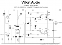
Thanks to the net, getting inspiration for such a thing is easy. Gordon Rankin for example still has his wonderful design article on "The Bugle" on his site: http://www.wavelengthaudio.com/bugle.pdf . We can take this topology and update the values for 300B and say 6SN7.
All we now need is the 300B to act as a driver to the MOSFET source follower output. To do this, we replace the output transformer with a 50W 3.3K resistor (wire wound non inductive). Then capacitor couple the 300B's plate to the gates of the MOSFET's. Those who are familiar with MOSCODE 300, will recognize the BIAS and OFFSET scheme here.
Sure, this is a bit "Frankenstein". After all, we are borrowing from Mr. Rankin and Mr. Kaye here. But is this not what our hobby is all about?
So how does this beast sound? It sound like what it is: a hybrid. But the cool thing here is that it retains the grunt of a 300B as well as its glorious midrange. The SRPP 6SN7 also works well here. Broskie has written extensively on the benefit of having the SRPP circuit working into a friendly load. Also please notice we are connecting the plate of the lower triode. This is mostly a taste thing. If you like, feel free to connect the 300B’s grid cap to the cathode of the upper triode.
The 300B also has an easier time of it. Not driving a transformer and difficult speaker loads, it is not breaking a sweat. Not to mention that we are running this (expensive) tube at ~ 50mA and ~ 300V on the plate so it will last for years.
Finally, all there amplifier stages are capacitor coupled – so any drift as a function of rolling and/or tube age will not affect operation. Which makes this a really nice DIY project. Have fun!
D.
This audio hobby is a funny old thing... It's a bit like cooking: you borrow insights and inspiration from all the good work others have done before you. Thanks to all those good folks, we can now snip a bit here and another bit there and then end up with some fun "new" circuits.
I started fooling with 300B's more than 20 years ago. And it is still one of my favorites. Alas we can only get ~ 8W or so from the old friend in an SE amp. To boot, the 300B's are expensive and so are good output transformers... Hundreds of $$$$.
But with hybrids, we can still get an old Hafler 200/220 on EBay and use it as a donor. Often for less than a few hundred bucks. We can of course also get some MOSFETs, heat sinks, power transformer and some power supply caps and build from scratch.
So this is the quest here: get the 300B sound and at the same time get enough power to drive most speakers. Not to mention rocking the house when you want to.
Thanks to the net, getting inspiration for such a thing is easy. Gordon Rankin for example still has his wonderful design article on "The Bugle" on his site: http://www.wavelengthaudio.com/bugle.pdf . We can take this topology and update the values for 300B and say 6SN7.
All we now need is the 300B to act as a driver to the MOSFET source follower output. To do this, we replace the output transformer with a 50W 3.3K resistor (wire wound non inductive). Then capacitor couple the 300B's plate to the gates of the MOSFET's. Those who are familiar with MOSCODE 300, will recognize the BIAS and OFFSET scheme here.
Sure, this is a bit "Frankenstein". After all, we are borrowing from Mr. Rankin and Mr. Kaye here. But is this not what our hobby is all about?
So how does this beast sound? It sound like what it is: a hybrid. But the cool thing here is that it retains the grunt of a 300B as well as its glorious midrange. The SRPP 6SN7 also works well here. Broskie has written extensively on the benefit of having the SRPP circuit working into a friendly load. Also please notice we are connecting the plate of the lower triode. This is mostly a taste thing. If you like, feel free to connect the 300B’s grid cap to the cathode of the upper triode.
The 300B also has an easier time of it. Not driving a transformer and difficult speaker loads, it is not breaking a sweat. Not to mention that we are running this (expensive) tube at ~ 50mA and ~ 300V on the plate so it will last for years.
Finally, all there amplifier stages are capacitor coupled – so any drift as a function of rolling and/or tube age will not affect operation. Which makes this a really nice DIY project. Have fun!
D.
Attachments
- Home
- Amplifiers
- Solid State
- Hafler DH-200/220 Mods