Its been awhile, but finally got back to working on some haflers myself.
I had a few dh200s and 220s around, so I went the route a few others here have done.
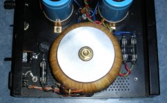
I took the power modules from a 220 amp, and upgraded them with new audio grade electrolytic and polyproplylene caps, with smaller pp bypass caps for the larger ones.
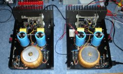
I then used 2 chassis from 200s to mount the modules into, and assembled them in a mirrored layout with the ac components as far removed from the dc sides as possible.
So far the mods include hammond torroids, non ferrous torroid retainers, moved the fuses to the output side of the transformers, 3 prong iec c14 ac socket and removable cord, switched ac-chassis ground, 18,000 mfd main caps, heavy duty toggle power switch at the rear, decent quality binding posts and rca inputs.
DC offset is <5mv per channel, and so far running the bias around 300mA.
They are a work in progress, but am pretty happy with the results so far, especially considering the relatively low cost involved.
With all the recent material posted here on the Haflers, I will definitely have to go through the posts for more ideas.
I had a few dh200s and 220s around, so I went the route a few others here have done.
I took the power modules from a 220 amp, and upgraded them with new audio grade electrolytic and polyproplylene caps, with smaller pp bypass caps for the larger ones.
I then used 2 chassis from 200s to mount the modules into, and assembled them in a mirrored layout with the ac components as far removed from the dc sides as possible.
So far the mods include hammond torroids, non ferrous torroid retainers, moved the fuses to the output side of the transformers, 3 prong iec c14 ac socket and removable cord, switched ac-chassis ground, 18,000 mfd main caps, heavy duty toggle power switch at the rear, decent quality binding posts and rca inputs.
DC offset is <5mv per channel, and so far running the bias around 300mA.
They are a work in progress, but am pretty happy with the results so far, especially considering the relatively low cost involved.
With all the recent material posted here on the Haflers, I will definitely have to go through the posts for more ideas.
Attachments
Its been awhile, but finally got back to working on some haflers myself.
I had a few dh200s and 220s around, so I went the route a few others here have done.
I took the power modules from a 220 amp, and upgraded them with new audio grade electrolytic and polyproplylene caps, with smaller pp bypass caps for the larger ones.
I then used 2 chassis from 200s to mount the modules into, and assembled them in a mirrored layout with the ac components as far removed from the dc sides as possible.
So far the mods include hammond torroids, non ferrous torroid retainers, moved the fuses to the output side of the transformers, 3 prong iec c14 ac socket and removable cord, switched ac-chassis ground, 18,000 mfd main caps, heavy duty toggle power switch at the rear, decent quality binding posts and rca inputs.
DC offset is <5mv per channel, and so far running the bias around 300mA.
They are a work in progress, but am pretty happy with the results so far, especially considering the relatively low cost involved.
With all the recent material posted here on the Haflers, I will definitely have to go through the posts for more ideas.
Nice implementation!
For sure no one can argue that it is not a double mono amp...
Changing the old electrolytics for better ones is a good investment return.
With the new transformers have you changed the supply voltage value?
If your transformers have separate secondaries (4 wires) then you can use a double bridge configuration for power supply. This bridge is only 5$ Each.
Fab
Hi Fab, thanks for the compliment.
The Hammonds have a slightly higher voltage output, but it only amounts to an extra 4vdc at the main caps, probably not enough to consider regulation.
They have multiple outputs, but I have them in parallel to double the current up to 6.66 amps per power supply.
I don't have any noise issues, but it looks like from previous posts that I should make a few ground changes, in regards to the input grounds, central ground, chassis ground etc.
I would also like to add some kind of in-rush limiter, and should replace the rectifier blocks.
It is next to impossible to tell from memory (4 years or so), but I am pretty sure that I prefer the older Wondercaps in my Pooge2 amp, but I didn't have enough of them to build the 2 mono versions.
The larger 4.7mfd caps are as big as those Mundorfs, and pose a mounting challenge for sure.
Kind of kicking myself now, I should have left that one intact and modded others so that I could compare back to back.
I have a spare 200 and 220 yet, so might just put them in one of them.
Also still very tempted to try the Musical Concepts boards, they are high on my list when funds permit.
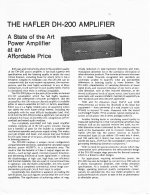
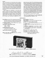
I was digging through my vintage promo material, and found this on the DH200s.
It was from back in late 70s, and printed on blue paper.
The Hammonds have a slightly higher voltage output, but it only amounts to an extra 4vdc at the main caps, probably not enough to consider regulation.
They have multiple outputs, but I have them in parallel to double the current up to 6.66 amps per power supply.
I don't have any noise issues, but it looks like from previous posts that I should make a few ground changes, in regards to the input grounds, central ground, chassis ground etc.
I would also like to add some kind of in-rush limiter, and should replace the rectifier blocks.
It is next to impossible to tell from memory (4 years or so), but I am pretty sure that I prefer the older Wondercaps in my Pooge2 amp, but I didn't have enough of them to build the 2 mono versions.
The larger 4.7mfd caps are as big as those Mundorfs, and pose a mounting challenge for sure.
Kind of kicking myself now, I should have left that one intact and modded others so that I could compare back to back.
I have a spare 200 and 220 yet, so might just put them in one of them.
Also still very tempted to try the Musical Concepts boards, they are high on my list when funds permit.
I was digging through my vintage promo material, and found this on the DH200s.
It was from back in late 70s, and printed on blue paper.
Attachments
I found a good place for Mundorf input capacitors.
An externally hosted image should be here but it was not working when we last tested it.
Those Mundorfs probably cost a good chunk of the original amp kit price
")
I believe I paid $475 Cdn for my kit at Advance Electronics in the late 70s.
Nice work on your amp, it looks very clean.
It looks like you have some Wima's on the cards.
Curious as to why the large value 10mfd bypass on the main caps?
Back in the old Pooge articles those were in the 4.7 - 5 range, and typically with a parallel .47 or .1 as well.
Cheapest, it really does not matter for this application, just make sure that you use the correct wattage for the size that you have selected,
something like 4.7K/2W for a 60V rail. (60 x 60)/4700 = 0.77W, so always double the wattage rating for what it is actually dissipating.
Rick
something like 4.7K/2W for a 60V rail. (60 x 60)/4700 = 0.77W, so always double the wattage rating for what it is actually dissipating.
Rick
Cheapest, it really does not matter for this application, just make sure that you use the correct wattage for the size that you have selected,
something like 4.7K/2W for a 60V rail. (60 x 60)/4700 = 0.77W, so always double the wattage rating for what it is actually dissipating.
Rick
Thanks Rick. I was going to use a 2W resistor. That should be more than enough, right?
Hi Fab
I missed the double bridge part, I am guessing that you mean running 2 rectifier bridges instead of a single one. Considering that I have mono versions of the amps, is there any benefit to going that route as opposed to installing a higer current bridge to handle the inrush created by the larger caps?
I understand that the transformer dual windings allow for a dual mono power supply setup within the same chassis, but mine are totally separate units.
I installed Vishay MKP1837 .01 mfd bypass caps on all of the larger caps, and they made a substantial difference in the top end.
At only around $1 each they are inexpensive enough be worth trying out.
On the main power supply caps I paralleled them with 4 mfd + .47 mfd caps.
I wanted to keep the rear speaker fuses, so I installed bypass caps on that as well.
These units have a mixture of caps in them, mostly low cost Daytons and whatever else I had lying around.
I didn't want to put anything fancy onto the boards, as they were from a previous owner modded unit that was scary looking, fortunately the boards are ok.
Here is a photo showing the tiny Vishays installed.
Attachments
Hi Fab
I missed the double bridge part, I am guessing that you mean running 2 rectifier bridges instead of a single one. Considering that I have mono versions of the amps, is there any benefit to going that route as opposed to installing a higer current bridge to handle the inrush created by the larger caps?
I understand that the transformer dual windings allow for a dual mono power supply setup within the same chassis, but mine are totally separate units.......
Hi msb64
Yes that is what I meant. 2 rectifier bridges at 35A each per amp is enough for these caps. 2 rectifier bridges is a better configuration for grounding.
Thanks
Fab
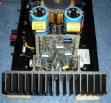
Did a few updates on my mono Haflers last week.
Updated to 35A Fairchild bridge rectifiers as per Fabs recommendation.
Rewired the primary side and added .5 ohm inrush limiters.
Removed ac line ground switch & connection as it made no difference in noise reduction.
The amps are near dead quiet, I can only hear a very faint hiss on the emits if my ear is right in front of them.
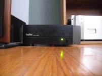
I am usually not into frills, but I missed my front "on" indicators.
Previously I had replaced the oem rocker switches with heavy duty rear mounted toggle switches.
I removed the DH200 chassis oem neon lamps and installed led indicators, and limited them to <10mA to prevent excessive glare.
Ended up passing on the bleed down resistors, as the amps already do so in seconds.
Not sure if there is supposed to be any other benefit to using them.
A local store called Metal Supermarkets cut me some nice .125 thick aluminum end plates, 4 of them was just over $20.
Breaking the units into 2 really helped enable me to beef up the power supplies.
Each replacement toroid is higher current output than the single oem transformer, plus effectively doubling up the main caps and increasing them to 18,000 mfd for a total of 72,000 mfd.
Needless to say, there is power to spare now
Updated to 35A Fairchild bridge rectifiers as per Fabs recommendation.
Rewired the primary side and added .5 ohm inrush limiters.
Removed ac line ground switch & connection as it made no difference in noise reduction.
The amps are near dead quiet, I can only hear a very faint hiss on the emits if my ear is right in front of them.
I am usually not into frills, but I missed my front "on" indicators.
Previously I had replaced the oem rocker switches with heavy duty rear mounted toggle switches.
I removed the DH200 chassis oem neon lamps and installed led indicators, and limited them to <10mA to prevent excessive glare.
Ended up passing on the bleed down resistors, as the amps already do so in seconds.
Not sure if there is supposed to be any other benefit to using them.
A local store called Metal Supermarkets cut me some nice .125 thick aluminum end plates, 4 of them was just over $20.
Breaking the units into 2 really helped enable me to beef up the power supplies.
Each replacement toroid is higher current output than the single oem transformer, plus effectively doubling up the main caps and increasing them to 18,000 mfd for a total of 72,000 mfd.
Needless to say, there is power to spare now
Attachments
I had some spare caps on hand, so changed the input caps to Soniccraft Gen 1 - 5 mfd with Gen1 - .1 mfd and Vishay - .01 mfd bypass caps.
I tried them first on my Dac 60 Lite outputs and it made a noticable difference, so I did the same for the Hafler inputs.
I also ran ground wires to the heat sink posts to insure good connectivity, and not have to rely on the electrical connection of the heatsink screws and heatsink - chassis connection.
While I had it apart, I installed all new insulators and thermal compound on the outputs, the old compound had turned to dust.
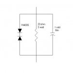
In regards to additional ground changes/upgrades, does this accurately represent what should be done if someone grounds the chassis to the line ground?
Should something similar be done for the RCA input grounds, but with a different value resistor?
I believe I have seen this cap ground configuration before, to help reduce noise from the transformer ground.
Does that noise show up as ac noise at the outputs, or does it degrade audio quality in a manner that is more difficult to detect?
Any input to help clarify the ground upgrades would be appreciated
I tried them first on my Dac 60 Lite outputs and it made a noticable difference, so I did the same for the Hafler inputs.
I also ran ground wires to the heat sink posts to insure good connectivity, and not have to rely on the electrical connection of the heatsink screws and heatsink - chassis connection.
While I had it apart, I installed all new insulators and thermal compound on the outputs, the old compound had turned to dust.
In regards to additional ground changes/upgrades, does this accurately represent what should be done if someone grounds the chassis to the line ground?
Should something similar be done for the RCA input grounds, but with a different value resistor?
I believe I have seen this cap ground configuration before, to help reduce noise from the transformer ground.
Does that noise show up as ac noise at the outputs, or does it degrade audio quality in a manner that is more difficult to detect?
Any input to help clarify the ground upgrades would be appreciated
Attachments
HiI had some spare caps on hand, so changed the input caps to Soniccraft Gen 1 - 5 mfd with Gen1 - .1 mfd and Vishay - .01 mfd bypass caps.
I tried them first on my Dac 60 Lite outputs and it made a noticable difference, so I did the same for the Hafler inputs.
I also ran ground wires to the heat sink posts to insure good connectivity, and not have to rely on the electrical connection of the heatsink screws and heatsink - chassis connection.
While I had it apart, I installed all new insulators and thermal compound on the outputs, the old compound had turned to dust.
In regards to additional ground changes/upgrades, does this accurately represent what should be done if someone grounds the chassis to the line ground?
Should something similar be done for the RCA input grounds, but with a different value resistor?
I believe I have seen this cap ground configuration before, to help reduce noise from the transformer ground.
Does that noise show up as ac noise at the outputs, or does it degrade audio quality in a manner that is more difficult to detect?
Any input to help clarify the ground upgrades would be appreciated
For the châssis to ground the diodes are not in series but in parallel.
There is no direct RCA ground connection to chassis as opposed to original
scheme.
The cap ground config is optimal but the heatsink may connect to chassis... For the sound effect of not doing so it depends also of everything else in your system....
Thanks
Fab
I had some spare caps on hand, so changed the input caps to Soniccraft Gen 1 - 5 mfd with Gen1 - .1 mfd and Vishay - .01 mfd bypass caps.
I tried them first on my Dac 60 Lite outputs and it made a noticable difference, so I did the same for the Hafler inputs.
I also ran ground wires to the heat sink posts to insure good connectivity, and not have to rely on the electrical connection of the heatsink screws and heatsink - chassis connection.
While I had it apart, I installed all new insulators and thermal compound on the outputs, the old compound had turned to dust.
In regards to additional ground changes/upgrades, does this accurately represent what should be done if someone grounds the chassis to the line ground?
Should something similar be done for the RCA input grounds, but with a different value resistor?
I believe I have seen this cap ground configuration before, to help reduce noise from the transformer ground.
Does that noise show up as ac noise at the outputs, or does it degrade audio quality in a manner that is more difficult to detect?
Any input to help clarify the ground upgrades would be appreciated
I have always wanted to try single point for every ground and power connection. It would be a big mass of wire coming off the boards and outputs though.
Power is just as important as ground, so treat them the same. Electrons don't care if the wiggle around on what we call ground and what we call a rail. At a minimum, I would feed the output section independently from the input section. Just lift the output facing end of the 68 Ohm resistors and wire it back.
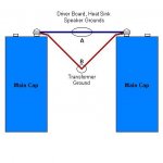
Fab, I made the change to indicate diodes in parallel, hopefully I got it right.
I find a diagram helps me to avoid possible mixups.
tvrgeek
"I would feed the output section independently from the input section. Just lift the output facing end of the 68 Ohm resistors and wire it back."
Thanks, checking into this now.
I believe R39 on the DH200 boards connects the input and output grounds, but I am not familiar with the setup on the DH220 boards, which I am now using for my mono units.
Attachments
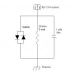
Fab, I made the change to indicate diodes in parallel, hopefully I got it right.
I find a diagram helps me to avoid possible mixups.
tvrgeek
"I would feed the output section independently from the input section. Just lift the output facing end of the 68 Ohm resistors and wire it back."
Thanks, checking into this now.
I believe R39 on the DH200 boards connects the input and output grounds, but I am not familiar with the setup on the DH220 boards, which I am now using for my mono units.
Msb64
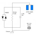
The diodes arrangement is correct but the connection of circuit is not. The chassis connection of the 110vac plug goes directly to the chassis connection which means the amplifier case. The circuit should be connected between the chassis and the main ground of capacitors bank.
Fab
My mistake Fab, I should have indicated the actual connection points earlier.
Corrections made, this should do the trick.
Would it be good practice to ground the chassis at a physically central point, or will any location do?
Thanks
The scheme is ok. However the diodes should be 3 to 5W....
Any location should do to electrically ground the chassis. Ensure to have a good connection though.
Thanks
Fab
tvrgeek
"I have always wanted to try single point for every ground and power connection. It would be a big mass of wire coming off the boards and outputs though.
Power is just as important as ground, so treat them the same. Electrons don't care if the wiggle around on what we call ground and what we call a rail. At a minimum, I would feed the output section independently from the input section. Just lift the output facing end of the 68 Ohm resistors and wire it back."
I checked the DH200 and DH220 driver board schematics, and do not see any 68 ohm resistors.
Judging by your statement that the power runs as important as the grounds, it sounds like both the power feeds and grounds for the input and output stages should be separated, and ran separately.
If that is the case, then the question would be where to actually make the break in the power and ground connections on the DH220 PC19 driver boards?
- Home
- Amplifiers
- Solid State
- Hafler DH-200/220 Mods