Dick West,Hafler Offset
Hi dick, I can see what you have done now, instead of padding the pot you have opted for the multiturn variety which is fine, point to remember that the total voltage across the pot will be about 120volts this will then dissipate 0.144 watts in this resistor, so it is wise that the pot rating can take this. The circuit you've used is fine
and as you have found out solved a load of unnecessary hassle.
regards
Anatech,matching
A colleague and I were doing a project based on the hafler circuit and produced
eight pairs of boards to be used in monoblocs, at the time we found a company that
would supply matched transistors at extra cost, since we had already fallen foul
of buying these different transistors off the shelf and finding their gain to be all over the place with little hope of finding suitable matches, the company supplying us were using professional testers because they supplied the industry, We were using a number of testers which were part of our professional multimeters, but like you we built our own tester to increase the current availability most multimeters only test
at 100 to 500microamps, nevertheless our meters corriellated very well with those of the proffessional one used by the supplying company, the experience with these boards, and all the other haflers i have modded and repaired, I think has given me a rather unique insight into the nature of the beast.[I have already answered your
question in post 448].The anomolies are that for no apparent reason you can have
an almost perfect board, but the next will be quite different with the same components, same gain matches etc, this exercise as i have been trying to illustrate
has happened repeatedly not for just one or two haflers but for most, so if my comments seem to smack of exasperation over this question you will now understand why!
regards
Hi Humble,
I re-read post 448 and found that I did understand it the first time. I was asking if you had swapped them channel to channel. My comments should make more sense now.
I can understand why you are exasperated, I've gone through similar things myself. I hate when I miss something very simple (because I overlooked it), but happy that someone else was able to point it out.
My experience includes restoring many amps that were "struck by technician", and worst, "struck by magazine modder". I've become very good at getting these things running again.
Anyway, good luck with it. One side note though. I find that I match much closer than commercial matched pairs.
-Chris
Anatech,Matching
Yes not only with other channel but with other boards from other spare haflers,
we matched all the I/P pairs to within a gain of 5 or better,I still have about 60
5551 and 5401 left floating around from years back not to mention 20 pairs of
5415 and 3440,[this project was years ago so is not current],the anomoly was that
for fun we matched some I/P pairs badly worse than gain of 20 but got an offset which was quite acceptable, and with new boards, new components etc, I'm afraid
the detail is a bit hazy now as so much water has flowed under that bridge,I think at the time we thought that maybe the problem was to do with the fact that the transistors in question were not all from the same manufacturer, implying some other oddity within the substrate and as I said before the predrivers were in some cases as low as 20 on gain, which might give a pulling effect on the I/P diffs,
The volage across the collector loads could vary by about 0.2volts I.E.from 2.2 to 2.4
volts which is more than can be accounted for by the resistor tolerances.
However I think we have kicked this one around far enough since no new input has been posted [I asked slowhands for comment but none yet], so the question remains for me an anomoly, mostly solved by trial and error, but wasting time and a lot of
transistors, today no-one would use those old video TO5 5415 3440 types except
to tarmac the road when so many good devices are available like sanyo 2SA1209
and 2SC2911, 150mhz 160volt, complementary.[used in my monoblocs]
So can we have a truce now about this question?
regards
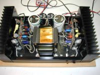
Dick West picture
Hi dick nice to see you finally got there, I note your thermal breakers are still connected, try connecting your mains directly and get a real surprise those extra
wires and breakers are sound destroyers particularly on 110volts supplies,I also observe the extra power supply caps, very sensible.Hope to see an extra pair of O/P
devices there one day.
Good luck
Hi Humble,
No need for a truce, we were never at war.")
Whenever anything causes me grief, I like to hunt it down until I understand why. Just my nature.
For what it's worth, I've noticed with beta's that measure the same I may still not be a match. The test jig I mentioned mimics a diff pair with no feedback so that a match can be confirmed at whatever voltage and current you want to run at. I was hoping the technique would help you in the future.
Best of luck in the future with these.
-Chris
No need for a truce, we were never at war.
Whenever anything causes me grief, I like to hunt it down until I understand why. Just my nature.
For what it's worth, I've noticed with beta's that measure the same I may still not be a match. The test jig I mentioned mimics a diff pair with no feedback so that a match can be confirmed at whatever voltage and current you want to run at. I was hoping the technique would help you in the future.
Best of luck in the future with these.
-Chris
Humble
Been there, done that. My present amp with the Musical Concepts PCBs has 6 MOSFETs per channel using heat sinks similar to those from the XL-280.
In the USA a company, Smart Devices, sells amps to motion picture theaters. For years they used the DH-220 PCBs with their version of amp chassis, toroid trannies, etc. They put the thermal breakers in series with the wiring that goes to the speaker protection fuse circuit. Thus, the amp can effectively be shut down by overheating and the speakers can be protected by the fuses. They did not put the thermal breakers in series with the AC.
I've considered doing this. What effect on the amp's output will the thermal breakers produce?
Hope to see an extra pair of O/P devices there one day.
Been there, done that. My present amp with the Musical Concepts PCBs has 6 MOSFETs per channel using heat sinks similar to those from the XL-280.
In the USA a company, Smart Devices, sells amps to motion picture theaters. For years they used the DH-220 PCBs with their version of amp chassis, toroid trannies, etc. They put the thermal breakers in series with the wiring that goes to the speaker protection fuse circuit. Thus, the amp can effectively be shut down by overheating and the speakers can be protected by the fuses. They did not put the thermal breakers in series with the AC.
I've considered doing this. What effect on the amp's output will the thermal breakers produce?
Hi Dick,
Not much. Marantz did this on some models.
Essentially, it's a set of contacts, like a relay. The only problem is that they can oxidize and you can't clean them. Replacement only.
Hi Humble,
Everyone around here knows that I take a very dim view of removing any protection circuits or devices in an amplifier. It's pretty darn foolish, and a bit arrogant (especially if you charge for that "service"). Don't do that. Buy new ones instead to replace the older parts.
That is the one thing that does get me steamed up. There is no argument you can make to compromise a safety feature.
-Chris
Dick West, breakers
Hi dick, you always have the choice between differentiating what protection is really necessary, I had already mentioned fuses that don't protect speakers, and a circuit from Randy Slone that would do a better faster job, as for these thermal breakers,
I personally have never had them operate at 75degrees, but I have had a demo where some DC time window speakers were being driven loudly with a large number of people in the dem room eventually the hafler started to run out of steam because
of overheating but the breakers were still operative, meaning as I said earlier ,Self limiting by the mosfets.Since the speakers are already fused and the mains is fused
just how much protection do you think you need?I refer to my earlier comment about using a decent mains cable with this amp of 2.5-4mm^ utterly pointless with the breakers still in circuit with their associated wiring I am suggesting that you try
doing without them if you want decent sound quality, you can always put them back
knowing the risk of your usage or abuse of this amp, I also mentioned a possibly better type of fuse that could be used, but all of these things are designed to get the max amount of current into the amp,since I spent many hours making up all sorts of power leads up to 10mm^ to gauge the effect on this amp I can assure you that the least resistance in the way of your mains means big gains in your sound.
The choice is yours!
regards
Anatech Diff tester
Hi Anatech,I'm sure many people would be interested in your SUPERTESTER,
including myself can you print the circuit? Also IANS forum member [meridian 605]
mentioned that he thought he had seen your name against some original Hafler mods, I couldn't find any of these only your particular "Critique" of other peoples postings I would be interested to read about your mods to see how they compare with those I have submitted, if there are any similarities, in case I have missed some
Could you remind me of the postings? remember I only came into the forum in May
07 Meanwhile can you get onto ERNOBORBELY audio and take a gander at the DC-102 power amp circuit printed in the Audio Amateur 4/93 this is the precurser to the later Haflers which of course were greatly simplified, point to note is the FET I/P
stage using no less than 16 devices, being fully symmetrical, with double cascoded
FET's and all sorts of regulation, followed by the ultralinear driver circuit as used in the hafler.. and guess what, for all this trouble, distortion only just better than 0.01%. Phil Rimmer of pantechnic [now defunct] was getting much better than that figure just using the hitachi clone circuit with a single long tailed pair of BJT's on the I/P but Selected drivers.Just remember that ERNO BORBELY is no tyro before you suggest he could have done better, you will need to read the whole article to fully
understand his philosophy, and why he has used so many devices, its very relevant to our previous discussion.
regards
Hi Humble,
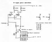
The thing is a test jig, not by any means a "SUPERTESTER". I have described it quite accurately and there isn't much to the thing.
The reason I described it rather than put up a picture (easier) is that my camera is missing and I'm in the process of redoing my home network. That included migrating from windows NT4 SP6 server to either the Beta of Microsoft Home Server or a Linux (probably RH 7) server. Never mind a new all in one printer and a few workstations that did have a sound card test system on it. So two workstations in flux on top of that.
So, just for you ('cause you are so special), I spent about 1/2 hour and hooked up my old scanner to my old Win '98 machine so I could scan this rather simple test jig. Keep in mind that it was designed and constructed in about an hour - and it seems to work very well. I sent some matched samples to a member with access to a Tektronix curve tracer to verify it's operation. He is located in Great Britian as well, so I've also put my money where my mouth is. They were sent airmail.
From what I have seen in practice, it is an improvement over simply measuring beta or IDSS and gate voltages.
Now, when it comes to mods, I do not speak out against any unless the compromise reliability, safety or are based on "magic parts". I use mostly the same user name, so go ahead and look. I believe I have been very consistent in my views for well over 30 years (in case you find someone who knows me, they can verify this). I have even taken a few manufactures to task over poor engineering and been vindicated. Have have not singled out any Quad or Hafler products for mods, just silly technicians.
I have been involved in servicing for over 30 years and I get to see the fallout from equipment being hacked. So I would think I'm in a decent position to understand what can happen as safety devices are bypassed. So, without installing another safety system to replace the one you are removing, you are doing a great disservice to your customer. Also, in Canada anyway, a line fuse or breaker is there to protect the connection between the unit and the wall outlet. If it also manages to protect internal components during a fault - GREAT! Other systems ought to exist to protect your load (speaker) which may be flammable once coil temperatures reach a certain point (believe me when I say that some certainly are!).
So, my stance is that if you feel that sound quality (as you perceive it) is more important than safety, you are a fool. Protection systems can be designed that have minimal to no impact on sound quality.
-Chris
Attachments
Anatech,Tester etc.
Thanks for that , pretty straightforward circuit. I understand your position about safety, but I have given alternatives in my posts, I do not consider myself to be irresponsible in this respect for example;I have before me a Musical Design circuit
from 1992 .I think they called themselves Musical Concepts, this circuit is all in name a Hafler with the exception of the drivers which are Fet's, there was two versions of this amp,D120, and D140,140 means 140 watts, also had split secondaries to give independant supply to each channel with a total of 50,000mfds per chann for the 140 model there are no fuses in the speaker feed, each set of H.T supplies are protected by 7 amp fuses and the nominal 10amp fuse for U.S.A. mains, no thermal breakers are used in this amp, and the heatsinks are about the size of the Hafler 280
One of my friends still uses this amp since 1993 trouble free I'm sure that if they felt
these breakers were unnecessary, because they had gone to so much trouble to give
the benefits of good power supplies and the most direct feed to the speakers,[no coil
or zobel] that this was the best approach for a good sound.Therefore to me the breakers are supernumery for the other reason that the Mosfets are self limiting,there are after all many better ways to use them if they are really necessary
,surely you must see that?The other point is that today's philosophy about sound quality is not the same as 1979,notwithstanding improvements in components,transistors, etc, I know of no manufacturer that would use disc ceramics
caps around an I/P stage because they are regarded as microphonic, or 5%-10%
tolerance resistors in any quality amp, or mains wire going all around the moon
This was overkill for the wrong reason, it just wasn't well understood back then
for the need to improve in a better way, but doesn't mean you can't subsequently
better a circuit , or layout,or add better components, well there it is, I have used the hafler circuit to Its best advantage and by god it shows!
regards
Hi Humble,
Yes, audio has come a long way. I do recognize that there are other ways of protecting the speaker. My point is merely that if you remove protection in one place, it must be covered somewhere else or by a different method. Still, I'd rather breakers than fuses.
One thing I have learned over the years is that components all fail. Each part has a failure rate, even when conservatively used. Also, what a manufacturer does and doesn't use in line with a speaker may have no bearing on sound quality. Rest assured that each one has a valid reason why the way they do things is better. I still don't buy the lack of protection. All I have to do is hold up the Bryston 4B or Proximity amplifiers as case studies. Each did not believe in any form of speaker protection, and each has taken speakers with them when they have (inevitably) failed.
Carver solved this problem nicely in their amplifiers. Low energy stored in the supply and AC shutdown. It works so well that often if an output shorts, nothing else is damaged. Not even the speaker. The speaker leads go directly to the amplifier unless it's a TFM, in which case they go through an LC network on the way.
All,
I reversed the current settings list in my jig in post #472.
-Chris
LM4702 Input
But as per the LM4702 (AN1645 application sheet), if a simple driver stage is used (as the one in the DH-200) the slew rate can be increased from 17V/us to 30V/us which is respectable (similar to DH-200). And if the power of the amp is less than 100W than it is even more respectable. Protection diodes can also be added for bias and output stage (as inthe DH-200). So I think that the question is still valid: How would it sound with an LM4702?
In fact, how the LM4702 sounds in already built amps?
thanks
djk said:It doesn't have enough drive current for the Hitachi FETs, not to mention bias or protection diodes, etc.
But as per the LM4702 (AN1645 application sheet), if a simple driver stage is used (as the one in the DH-200) the slew rate can be increased from 17V/us to 30V/us which is respectable (similar to DH-200). And if the power of the amp is less than 100W than it is even more respectable. Protection diodes can also be added for bias and output stage (as inthe DH-200). So I think that the question is still valid: How would it sound with an LM4702?
In fact, how the LM4702 sounds in already built amps?
thanks
http://www.national.com/an/AN/AN-1645.pdf
I am not impresed by this note, or the $15.30 (in 25 lot) part.
Driving only one pair of FETS gives a slew rate of only 12.5V/µS (without an extra driver). No protection diodes in sight, no cap across the bias circuit to prevent bias modulation.
I'd like to see a universal drive board to replace the Hafler ones, but this part would not make my list.
djk said:http://www.national.com/an/AN/AN-1645.pdf
I am not impresed by this note, or the $15.30 (in 25 lot) part.
Driving only one pair of FETS gives a slew rate of only 12.5V/µS (without an extra driver). No protection diodes in sight, no cap across the bias circuit to prevent bias modulation.
I'd like to see a universal drive board to replace the Hafler ones, but this part would not make my list.
How about this one, then?
http://www.national.com/pf/LM/LME49710.html
http://www.national.com/an/AN/AN-1651.pdf
Or this?
http://www.national.com/pf/LM/LME49870.html
Both of these parts will do a slew rate of 20 V/us, and the latter can swing 44 volts.
I've always respected your opinion on solid state topics, djk. What would you suggest?
Thanks!
- Home
- Amplifiers
- Solid State
- Hafler DH-200/220 Mods