it's simple as this
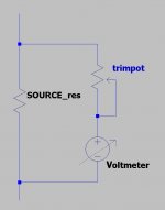
source resistor or resistor in series with rail ( lazy to look at schmtc)
just calc do you have enough voltage across said resistor to have enough current through voltmeter for mid position of needle , which is half of declared current
source resistor or resistor in series with rail ( lazy to look at schmtc)
just calc do you have enough voltage across said resistor to have enough current through voltmeter for mid position of needle , which is half of declared current
Attachments
Last edited:
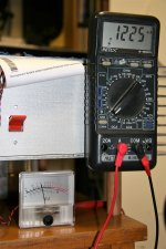
I've measured current through VU meter.
It is 0.1225mA or 122.5uA, in a quite good correlation with calculated value, which is 0.1V/760 Ohm as is 131.5uA. It is slightly higher than measured value, because of serial impedance of my METEX multimeter.
It is 0.1225mA or 122.5uA, in a quite good correlation with calculated value, which is 0.1V/760 Ohm as is 131.5uA. It is slightly higher than measured value, because of serial impedance of my METEX multimeter.
Attachments
.....
But I must to know those cheap ammeters internal resistance to choose the proper one.
exactly
if that info is missing , buy just one and measure it
There was an accident.
I was tried to raise quiescent current a little, while monitored changes with those VU meters. Then there was some work and phone calls I must have to answered, so it was remained alone without supervision. Know, it is my fault.
So as I come back, there was a huge DC offset at outputs, 7VDC and 5VDC on other half (channel).
I switched off immediatelly, and began to trace, what could happened?
And what was damaged.
It wasn't a really good feeling, I can say.
First I've measured resistance between drains of Sony VFETs.
It was about 2-2.5 Ohm, as usual in switched off.
So definitely not short circuit.
I think even in California it was possible to hear how the rock rolled out about my heart. Isn't it, Papa?
Further investigation showed, one of the channels lost its negative PS voltage.
It revealed later, it was because two 0.47 Ohm resistor between supply caps went south. They were almost open circuit in Mohm range.
Replaced them, a big breath and switched on with light bulb series with AC line.
Everything went well.
Sonido speaker, which was connected also survived, because it was connected between positive terminals of two channels.
It works flawlessly now.
I can't understand, why those two resistors must have to die?
On a somewhat similar note (initial current) which in this case is probably a whole lot more!
http://www.diyaudio.com/forums/pass-labs/124889-b1-buffer-preamp-145.html#post5170015
Tony.
http://www.diyaudio.com/forums/pass-labs/124889-b1-buffer-preamp-145.html#post5170015
Tony.
Yes, VU-meters showed an initial over voltage on R32.
These were not calibrated.
Also, DMMs too lazy to show initial peak correctly.
Perhaps I can measure it with one of my scope.
In this case Tek 2440 would be appropriate I think.
But I must pay attention to measuring arrangement, I can't connect ground lead to any legs of R32 of course.")
These were not calibrated.
Also, DMMs too lazy to show initial peak correctly.
Perhaps I can measure it with one of my scope.
In this case Tek 2440 would be appropriate I think.
But I must pay attention to measuring arrangement, I can't connect ground lead to any legs of R32 of course.
can you phone him and ask are my drivers still at his shelf ..... C45 Lowthers (needing new spiders and soldering of VC ends) and bare baskets of Electrovoice 12trxb (as base for 12" extended/full rangers)
my emails are evidently finishing in black hole , or something ......
my emails are evidently finishing in black hole , or something ......
- Status
- This old topic is closed. If you want to reopen this topic, contact a moderator using the "Report Post" button.
- Home
- Amplifiers
- Pass Labs
- Gyuri's Pass SONY VFET2 build.