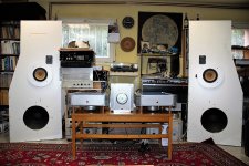
It sings for more than three hours now.
I'm a happy man, with two Sony VFET amp.")
Excellent news bravo Gyuri !
Most impressive properties of Sony VFET:
First of all, it has a damned good sound, of course.
Second, there is no noise!
No hiss, no buzz at all, even if I put my ears on the loudspeaker.
This is the quietest one of all I've ever built.
You can not say quietest, it is not the proper expression.
There isn't any noise at all.
Tremendous.
First of all, it has a damned good sound, of course.
Second, there is no noise!
No hiss, no buzz at all, even if I put my ears on the loudspeaker.
This is the quietest one of all I've ever built.
You can not say quietest, it is not the proper expression.
There isn't any noise at all.
Tremendous.
I have a question about bridged mode.
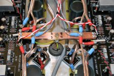
As you can see it from picture above, (sorry for unusual bad quality, I will make better ones.) there are four bridge rectifiers and four cap banks for the two channels.
It means, there are no common ground reference for two independent amp, other than ground of inputs.
One of my solutions for this in similar cases, an external copper rod between negative speaker terminals.
Perhaps it would be better if I put it internally, between ground points of the two PCBs.
Any thoughts?
copper rod is good enough , if speaker wire coming to negative connector is fat enough
regarding bridging - you want to simply bridge them ( feeding balanced signal etc.) or you want to make them truly differential ?
in case of later - you need pulling both R4s from ground and connect their ends together (in series)
of course , observing DC offset tendencies is a must
regarding bridging - you want to simply bridge them ( feeding balanced signal etc.) or you want to make them truly differential ?
in case of later - you need pulling both R4s from ground and connect their ends together (in series)
of course , observing DC offset tendencies is a must
Hi ZM,
Thank you for your answers, and questions as well!
Must have to say, I was thinking on first case only.
Most part of my system is true balanced, so I was thinking on first case only.
What could be the benefits of fully differential layout you suggested?
Can I use it in this way as a stereo amp?
Or can I use it in differential mode, and can I revert it by a switch connected in mids of R4s and ground?
Suspect in this case it isn't enough simply switch on, must be setting it from DC viewpoint.
.............
-What could be the benefits of fully differential layout you suggested?
.........
-Or can I use it in differential mode, and can I revert it by a switch connected in mids of R4s and ground?....................
-Suspect in this case it isn't enough simply switch on, must be setting it from DC viewpoint.
-benefits - same as comparing usual mumbojumbo balanced vs. SUSY (differential error correction)
-yes , switch will do
-dunno - I didn't tried exact amp in vivo so I can't tell - so you need to check is there any DC offset wandering when switching from one mode to other
naturally - switching while amp is off , just in case
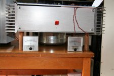
So I would like to use a meter to constantly monitoring bias current on both (four) channels.
There are many kind of cheap Chinese round analog ammeters on Ebay, but I don't know, how to choose a proper one.
I would welcome any advices!
It is just for testing purposes connected to R32:
There are many kind of cheap Chinese round analog ammeters on Ebay, but I don't know, how to choose a proper one.
I would welcome any advices!
It is just for testing purposes connected to R32:
Attachments
-benefits - same as comparing usual mumbojumbo balanced vs. SUSY (differential error correction)
-yes , switch will do
-dunno - I didn't tried exact amp in vivo so I can't tell - so you need to check is there any DC offset wandering when switching from one mode to other
naturally - switching while amp is off , just in case
I'm just have implemented switches for switching balanced vs. differential.
These are works great, even on the fly.
There is no or just slight changes in DC viewpoints.
But I must have to say, I don't hear any differences soundwise between balanced and differential.
Attachments
How's about this, for example?
DC 0-200uA Round Analog Ammeter Panel AMP Current Meter Dia. 90mm Direct Connect | eBay

DC 0-200uA Round Analog Ammeter Panel AMP Current Meter Dia. 90mm Direct Connect | eBay
any Weston with full tilt current in range of 100uA to 1mA will do
that , if you're buying voltmeter practically and connecting it across some resistor to indirectly measure Iq
if you choose ampermeter , then ampermeter is ampermeter - needs to be fully operational for current indicated on scale , already having implemented own shunt resistor
that , if you're buying voltmeter practically and connecting it across some resistor to indirectly measure Iq
if you choose ampermeter , then ampermeter is ampermeter - needs to be fully operational for current indicated on scale , already having implemented own shunt resistor
Last edited:
What I've thought, I will simply parallel an appropriate micro amp meter with R32.
Those VU meters are in this configuration, they shows bias current pretty well.
These have about 760 Ohm resistance.
So most of the current goes through R32, and a little portion drives VU meters.
My problem is, I don't know which cheap micro amp meter has similar parameters.
And I do not want to spend money blindly, even if it is little.
- Status
- This old topic is closed. If you want to reopen this topic, contact a moderator using the "Report Post" button.
- Home
- Amplifiers
- Pass Labs
- Gyuri's Pass SONY VFET2 build.