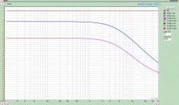
Okay here they are. I had the scope attached to the output and grid. Used a precision multimeter to measure signal strength. The soundcard was used as the signal source but the soundcard input was not connected.
The input signal showed a slight decay at 40kHz of -0.08dB but was constant at the lower frequencies at 166.7Vrms. Attached are the grid and output plots vs. frequency for several attenuator steps. What is clear is that the grid is also showing the HF rolloff. The 12b4 is maintaining constant gain of 5.87 or 15.3dB within all of the test conditions. In my limited knowledge, this eliminates the Gyrator/12b4 as the culprit and puts the focus on the stepped attenuator/input circuit.
I will run some sweeps at different steps directly from the attenuator with no circuit attached in a little while.
Attachments
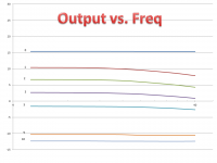
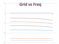
The 12b4 is maintaining constant gain of 5.87 or 15.3dB within all of the test conditions. In my limited knowledge, this eliminates the Gyrator/12b4 as the culprit and puts the focus on the stepped attenuator/input circuit.
Exactly!
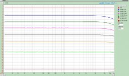
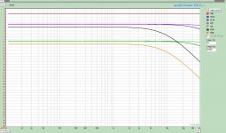
Interesting stuff. Attached are several plots. The first showing the frequency resp of the stepped attenuator only. i.e. disconnected from the circuit. The test conditions are exactly as the earlier post.
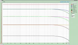
Thinking I was ripped off when I bought this thing, I pulled out my well trusted and generally accepted as good Alps Blue. In the second plot I compared the Alps to the Stepped Attenuator. The Alps is even worse and does not improve with increasing attenuation liked the stepped.
If anyone is thinking that if we see this performance with the mid priced attenuators, just buy a radioshack cheapie, well think again. The third plot is one of those.
P.S. It would be interesting to build a discrete voltage divider (attenuator). i.e. two resistors only and test.
Attachments
Last edited:
Hello Scott,
So many variables it is difficult to isolate all but one.
An attenuator is just a voltage divider there are no inductors or capacitors creating any filter poles in there. The circuits in the sound card must be playing a part. The low impedance input was worse!
I recall many years ago my father explaining the application of a Vacuum Tube Volt Meter.
As you say interesting results, thought provoking results.
DT
All just for fun!
Last edited:
You can use something like this:
http://wavebourn.com/maat/MAT_Assembly.pdf
http://wavebourn.com/maat/Mattrix_Attenuator_Applications.pdf


$50 + shipment from Israel.
http://wavebourn.com/maat/MAT_Assembly.pdf
http://wavebourn.com/maat/Mattrix_Attenuator_Applications.pdf
$50 + shipment from Israel.
I would think that would have even more capacitance than the stepped attenuator. I believe DT is correct.
I am running some curves on a simple three resistor attenuator and getting similar results. I looking at three impedances so I may not finish measureing tonight.
I am running some curves on a simple three resistor attenuator and getting similar results. I looking at three impedances so I may not finish measureing tonight.
Last edited:
I would think that would have even more capacitance than the stepped attenuator.
No, actually that complex matrix is to control relays only! The purpose of such complex control is to simplify the attenuator itself, unlike a stepped attenuator where all resistors are always connected to each other adding own errors with each step!
It is a ladder type attenuator, and it has 2 lead-less resistors connected in any position, through micro relays that have very low capacitances. It was designed by my friend in Israel, for himself, but in order to make it cheaper he run more. Main advantages are wide frequency response, and what is more significant, precision tracking between both stereo channels.
He made 2 options of control of relays: diode matrix to control by conventional multi-step switch, and a tiny microprocessor that senses position of an ordinary 5 KOhm potentiometer.
Also, he has different resistance values.
Last edited:
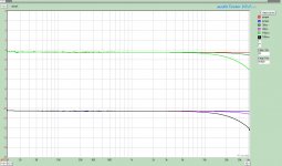
Ok it didn't take as long as I thought. I made three simple attenuators using three resistors each. That gave me three levels of attenuation, 0dB, -3.5dB, and -9.5dB. The three attenuators were 45k, 99.9k, and 665k.
0dB shows no roll-off and no loss of gain in the three configuration.
The 45k attenuator was the best measured. No loss of gain and minial roll off.
The 665k was the worst. Roll-off the most severe and there was over 1dB of signal loss. (I checked this result and verified my set-up hadn't changed)
The question is what part of the soundcard is causing this? and why? I am thinking that it has to be the output of the sound card since I get the same results when the 12b4 buffer is inserted into the equation. But why would the impedance that the soundcard's output sees change? I would think its value would be set by the total resistance of the attenuator.
FYI I physically measured the radioshack attenuator and found it to be 500k even though it says 50k on the case.
P.S. Wavebourn I see your point of not having the resistors floating. May consider it seriously once I understand what is happening here.
Attachments
Last edited:
Hello Scott,
What do you think for a follow up test?
What if one at a time then both the soundcard output and input are balanced and buffered (AKA Millett Soundcard Interface). Or Simplistic single end JFET buffer.
The Simplistic JFET RIAA has a nice buffer at the output.
DT
All just for fun!
What do you think for a follow up test?
What if one at a time then both the soundcard output and input are balanced and buffered (AKA Millett Soundcard Interface). Or Simplistic single end JFET buffer.
The Simplistic JFET RIAA has a nice buffer at the output.
DT
All just for fun!
There is a trend that shows the higher impedance your attenuation is the more it droops. That indicates a progressively longer time constant. There is certainly some capacitance and RC is formed. If you apply a capacitance mode DVM on the card's input what does it show? As DT says, if it will be buffered and won't droop, then its that input.
Salas, You are correct. I will measure the capacitance with and without the cable this evening. Based on the data, it would indicate, in this soundcard configuration, the problem is more associated with a RC network being set up with the soundcards ouput, as the attenuation issue is the same whether the signal is buffered or not. While buffered, the signal exhibits the same HF roll-off behaiviour at the grid of the tube. In the manual test shown previous, the sound card input was disconnected.
Nick,
Would you test your tracker in the following way.
Make an attenuator of three equal resistors with the total value of around 500k. Measure the frequency response directly with the soundcard the soundcard input cable set at 2/3 attenuator value. I am curious to compare result directly. If you can sample at 96k would be ideal but 48k should also give enough info.
Thanks
Scott
The capacitance of the Sound Card Interface reads 180nF. I don't know if I believe it or not. I can't get a stable reading on the input of the soundcard.
DT.
With the Sound Card interface, I get a similar round off. Particularly with cables. If I hook up with jumpers less than 1 foot in length roll-off disappears. I am going to make up some different cables tonight.
DT.
With the Sound Card interface, I get a similar round off. Particularly with cables. If I hook up with jumpers less than 1 foot in length roll-off disappears. I am going to make up some different cables tonight.
Solved! (or I think)
Rather interesting problem with what I hope will be good information for those following. The thread started as a question regarding the high frequency performance of a gyrator loaded 12b4. The quest twisted around into looking at the attenuator, to soundcard, and finally to the cables used to measure.
In this measurement I am using the Pete Millet Sound card interface with balanced connection to the 1616m soundcard. On the output of the soundcard, I have a 1meter length of RG58A/U with BNC connections. I used jumper wires to connect the BNC output connection to the attenuator so the output sees a fixed 100k load.
For the variable, I used two different lengths of the same RG58A/U cable with BNC's and for the experiment control, I directly connected to the sound card interface input using the jumper leads.
Attached is a measurement of a 100k simple attenuator made of three resistors. As can be clearly seen, the longer the cable the lower in frequency the roll-off starts. The 1.5meter cable measure 187pF and the short 30cm cable measures at 72pF. The jumper cables in close prox to each other are at the limit to my DVM at 49pF. Just the test leads read 43pF.
Although I have yet to run the experiment, given the identical performance of the soundcard interface and the direct connected 1616m soundcard in the previous experiments, I am hypothesising that it will perform to a similar level of performance. It would be nice to measure low level signals with the noise floor that the 1616m provides.
Attachments
- Status
- This old topic is closed. If you want to reopen this topic, contact a moderator using the "Report Post" button.
- Home
- Amplifiers
- Tubes / Valves
- Gyrator Frequency Response?