I just calculated a bit; for 35 pF Miller (4.8 pf x 6.5 gain) and 40 kHz corner frequency there should be 100K signal source resistance.
For 23.5K as you stated above, to roll off on 40 KHz Miller capacitance should be around 150 pF. It can't be so high; that means you have some extra roll - off on output. But as you may understand, for 1K internal resistance of the tube it should be loaded on 3,500 picofarad to show such roll-off!
For 23.5K as you stated above, to roll off on 40 KHz Miller capacitance should be around 150 pF. It can't be so high; that means you have some extra roll - off on output. But as you may understand, for 1K internal resistance of the tube it should be loaded on 3,500 picofarad to show such roll-off!
Last edited:
That D1 doesn't have noise effect seeing a transistor's base Wavebourn? Can it better be 2XLM329 in series?
It has some noise effect, but the question is, how significant it is. You may see the cumulative effect of all noise sources on the picture.
Bypass the cathode Leds with 1000uF and see for effects on FFT/subjective.
Multiply cathode resistance on 6.5 amplification factor, to get an addition to resulting internal resistance...
It is some mystery. I can think of huge inductance of that 4.7 uF capacitor in gyrator, but I don't think it is so.
If you remember it, in Tower-III I analyzed similar stages loaded on gyrators: 6N1P and 6P15P. There were even pictures, of a perfect triangle of 300 KHz 120V P-P.
Last edited:
Multiply cathode resistance on 6.5 amplification factor, to get an addition to resulting internal resistance...
It is some mystery. I can think of huge inductance of that 4.7 uF capacitor in gyrator, but I don't think it is so.
If you remember it, in Tower-III I analyzed similar stages loaded on gyrators: 6N1P and 6P15P. There were even pictures, of a perfect triangle of 300 KHz 120V P-P.
I wonder what are the characteristics of the Mic/HiZ input on that Emu card.
Has a 1Meg input impedance and a little higher noise floor.
Your suggestions are worth a try tomorrow.
I need to reread my post, but the problem, at least with the HF roll off was solved when I switched to the HiZ input. The last plots are of the Gyrator loaded 12b4 output. Freq responce is flat to 20kHz. The little bump above 20kHz is an error in the cal file.
I figured that the reason I didn't see this issue with the Riaa was that it did have a low Zo. The output impedance of the 12b4 is somewhere around 1k2. Hence I did not see a roll of with the Riaa and did with the 12b4. The roll-off dissappeared on the 12b4 when I switched to the hiZ input on the card.
I should pull my systems 12b4 preamp and measure it tomorrow with the two different inputs.
P.S. I think it is time for me to get some sleep.
I should pull my systems 12b4 preamp and measure it tomorrow with the two different inputs.
P.S. I think it is time for me to get some sleep.
Last edited:
Hello SGregory,
If you would, tell us how your device under test attaches to your test gear. The 1616 E-Mu has balanced inputs and outputs and your DUT is single end. You have a stepped 100K attenuator at the DUT input.
I am using an E-Mu 1212 that has a different daughter card than the 1616. I also am using a Pete Millett test interface that outputs balanced to the sound card.
DT
All just for fun!
Hey DT,
I use the Pete Millet interface when I am looking at voltages above 1-2Vrms or unknowns. As mine is built the interface noise floor is running about -130dB or so. I can get lower going direct. I just throw a zener in to protect the input above 3Vp.
The 1616m can either be balanced or unbalanced. The noise is much better using balanced, but I don't have a good balanced probe set-up yet. Would like to get a transformer. Right now I use a TS to RCA connector and the a RG58/U cable with BNC/RCA convertors.
Scott
P.S. The stepped attenuator is just an expensive 100k resistor right now and is setting the input impedance to 100k. Not attenuating with it at this point. I didn't have time today to mess with raising the input signal and attenuating but will in the next day or so.
Last edited:
Salas,
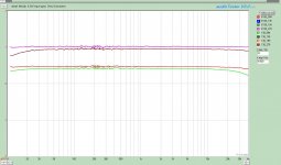
I didn't have a 1000uF cap to play with so I parralled (sp) three 220uF caps for 660uF total. I didn't see a significant improvement in THD or noise floor. I did see a marked improvement in Freq Response though. The attached sweep is with 130V anode varied between 9.4mA bias and 27.8mA bias both Bypassed and UnBypassed.
Bypassing the LEDs appears to remove the remaining local feed back associated with stringing that many LEDs together. Freq Response is much flatter bypassed at both extremes. What I find interesting is the behavior unbypassed. At low Bias the LF response is better but suffers some increased HF rolloff, At a high bias current the LF suffers some increased rolloff but the HF is better. I assume that the improved HF rolloff is a result of a lower Ra at those currents.
In the Index B means bypassed. The first three numbers are Anode voltage and the second numbers is bias x10. I measured a couple of bias settings in between but it made the graph too cluttered.
If you note the Y axis none are real bad. and with in the case of HF the roll-off seen is weill above audible.
I should comment that the sweeps were conducted with the exact same input signal Vrms of 166.9mVrms. The changes in gain are due to the circuit and tube operating point. In the graph 1dB= 1Vrms. Sorry but it is an error in my cal file, as are the squiggles. The tube used is a GE JAN12b4a calculated mu is about 6.
Attachments
Last edited:
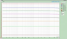
Here is some more interesting data. In this set of curves where I stepped the attenuator downward. I would have thought that as I increased attenuation, the HF rolloff would have increased. Instead, the roll-off decreased with increased attenuation. I measured the resistance of each step and the source impedance remained spot on 100k.
In these sweeps, 130Va, 27.9mA bias. LED's bypassed 660uF. 0dB=1Vrms output. 0.166Vrms input.
In these sweeps, 130Va, 27.9mA bias. LED's bypassed 660uF. 0dB=1Vrms output. 0.166Vrms input.
Attachments
Last edited:
Yep. Have the old school tools too. ;-), I assume you want to test some square waves.
Not necessary. Would be enough to check frequency response by sine waves of different frequencies.
")
- Status
- This old topic is closed. If you want to reopen this topic, contact a moderator using the "Report Post" button.
- Home
- Amplifiers
- Tubes / Valves
- Gyrator Frequency Response?