Next try ... an assessment: The power supply is perhaps too weak. The roofs of the rectangle is a break.
I think I understand now
The power supply I'm using is THIS one and believe me, it's not too weak. Set to +/-15VDC up to 2A current.
If you are looking at the clipping in post #13, it is supposed to do that. That is diode clipping, not power supply.
I believe you 
And yes, I did realized that the diodes limiting the signal.
But have you ever tried to simulate the circuit with a weak power supply? It's amazing what happens to the signal when the circuit operates in the border range. I simulate the most of my circuits with LT-Spice (Linux and wine).
And yes, I did realized that the diodes limiting the signal.
But have you ever tried to simulate the circuit with a weak power supply? It's amazing what happens to the signal when the circuit operates in the border range. I simulate the most of my circuits with LT-Spice (Linux and wine).
Moving on.
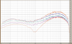
Next step is to check the frequency response of the tone controls and compare to the simulation. I tried to use RMAA but it will not let me record each new setting of the tone controls at the same volume setting. So I used Adobe Audition, recording a white noise sample through the preamp. I've used this program for this kind of analysis before and I believe it does a better job than RMAA.
Here is the combined response:

Gain at ~25%, volume set to ~50%, each of the tone controls advanced equally - 0%, 25%, 50%, 75%, and 100%. The same as I did in the simulation in post #9. The Bright switch is 'on'. One difference from the simulated response is that I'm using a 10K pot for the High tone control, when it is supposed to be 25K (I don't have a 25K pot on hand yet).
Overall, not a bad match. Some good variability in the tone settings, with more than 6db for each.
Next step is to check the frequency response of the tone controls and compare to the simulation. I tried to use RMAA but it will not let me record each new setting of the tone controls at the same volume setting. So I used Adobe Audition, recording a white noise sample through the preamp. I've used this program for this kind of analysis before and I believe it does a better job than RMAA.
Here is the combined response:

Gain at ~25%, volume set to ~50%, each of the tone controls advanced equally - 0%, 25%, 50%, 75%, and 100%. The same as I did in the simulation in post #9. The Bright switch is 'on'. One difference from the simulated response is that I'm using a 10K pot for the High tone control, when it is supposed to be 25K (I don't have a 25K pot on hand yet).
Overall, not a bad match. Some good variability in the tone settings, with more than 6db for each.
Last edited:
I spent most of the day yesterday either measuring and listening to this preamp. I'm now satisfied that it is performing the way I intended.
I made a few small changes:
Added a 47pF cap from the gate to the source on Q1.
Increased the gain of the input stage to ~10. I did this because I reduced the gain of the second stage by adding a 100K resistor from the wiper of the 'gain' pot to its low side. This effectively cuts the value of this pot in half (from 100K to 50K) and gives an approximation of reverse audio taper. My listening tests and measurements said that this was a worthy change, giving unclipped signal up to ~50% of the pots travel.
With an input signal of 100mVrms, the output with all controls maxed is ~1.8Vrms. At first I thought this might be too low, considering that the maximum gain setting for 'clean' is 50%, but having driven a power amp/speaker combo, I can say that I was mistaken. Still lots of volume on the clean setting.
The tones really have broad effect and tailor the sound very well. I was on the money concerning the midrange null - very good effect with high at max and the bright on.
I'll post the final schematic shortly. I need to make a couple of changes to the board layout and then I'll post that too, for anyone out there in TV land in need of a very righteous preamp.
Well worth the time and effort to get this preamp right. I have installed it in a cab with a Patchwork power amp module putting out about 50 watts and it is actually better than I expected. The tone control is awesome and I was right on the money about that midrange null - great effect, especially with the gain maxed.
Final schematic: View attachment Guitar Preamp.pdf
Since the preamp is done, I'll carry on with some of the details about the cab it went into. More soon.
Final schematic: View attachment Guitar Preamp.pdf
Since the preamp is done, I'll carry on with some of the details about the cab it went into. More soon.
So, here's the preamp in action: YouTube - DIY Guitar Amp 2
Some "non-solid state" type content coming, but it's one posts so bear with me.
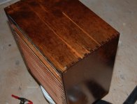
The cab it went into is G1S plywood, finger jointed at the corners:

Special walnut Minwax stain plus a few coats of tinted satin urethane.
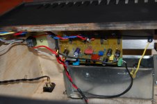
Peek at the power amp:

an older Patchwork module that I lowered the gain on and bumped up cdom to a wopping 220pF to make it run stable at the lower gain.
Also seen is the sheet metal preamp enclosure which seems to make a big difference to the amount of noise pickup.
Off to the left there is a relay that completes the circuit to the speaker. It is delayed by an RC timer on power up so the speaker is not 'popping' from the supplies coming up. It releases immediately when the power switch is turned off to cut the speaker out so it doesn't make those annoying noises when the supplies drain.
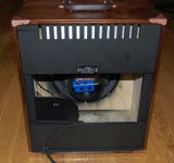
The power transformer and supply are under the black sheet metal cover:

neat and tidy.
Some "non-solid state" type content coming, but it's one posts so bear with me.
The cab it went into is G1S plywood, finger jointed at the corners:

Special walnut Minwax stain plus a few coats of tinted satin urethane.
Peek at the power amp:

an older Patchwork module that I lowered the gain on and bumped up cdom to a wopping 220pF to make it run stable at the lower gain.
Also seen is the sheet metal preamp enclosure which seems to make a big difference to the amount of noise pickup.
Off to the left there is a relay that completes the circuit to the speaker. It is delayed by an RC timer on power up so the speaker is not 'popping' from the supplies coming up. It releases immediately when the power switch is turned off to cut the speaker out so it doesn't make those annoying noises when the supplies drain.
The power transformer and supply are under the black sheet metal cover:

neat and tidy.
Do you have a PDF file to print? I need the dimensions of the circuit board.
Soon, it's not done yet. I need to include the changes I made when 'voicing' the preamp.
Congratulation to the great guitar amp.
You seem a better craftsman than to be a musician.So do I.

Thanks,
That wasn't me playing - I can't play at all - the best I can produce is just some random noises.
Personally it sounds me to hard in the heights, but typical for a transistor amplifier.
My parts came yesterday, we'll see how my idea sounds.
I expect that is the standard reply, since everyone believes that tube amps are better than SS amps.
What I can say is that to judge it, you need to hear it first hand, not recorded (by a tiny point and shoot camera with internal mic). Believe me, it sounds quite a bit better in person.
Good luck with your project.
- Status
- This old topic is closed. If you want to reopen this topic, contact a moderator using the "Report Post" button.
- Home
- Live Sound
- Instruments and Amps
- ☠ Guitar Pre. Clean With Some Sizzle.
