Do you implement high output impedance of power amp? It is very important for guitar sound to have damping factor about 1! And no, low damped guitar speaker behaviour cannot be emulated with sophisticated EQ.
Also as your power amp is low powered - 30W / 8 Ohms, power amp should soft-clip. Do you have soft-clipping circuit? (I attach one)
Also as your power amp is low powered - 30W / 8 Ohms, power amp should soft-clip. Do you have soft-clipping circuit? (I attach one)
Attachments
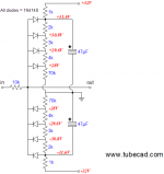
As Teemuk also noticed, your soft clipper needs 64Vpp to work.You connect it to the input of poweramp.
+ / - 32V voltages should be your poweramp voltage rails.
Sure, in simulation it will round peaks beautifully, but such signal level is not realistic if coming from a preamp.
And even if you got it, it would be way too much for a power amp, which usually have gain around 20X .
Not a bad design, that's not the point, but you should recalculate values for, say, 5 or 10Vpp signals so it can realistically work and then it will have to be padded down (master control) to power amp friendly values.
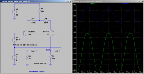
That said, a couple diodes across the master/out volume pot will also round peaks beautifully:
An externally hosted image should be here but it was not working when we last tested it.
See it for yourself, just simulate whatever's to the right of C4 and use standard silicon diodes (1n400x/1N914/1N4148) , feed 500/1000/2000/4000mVpp of triangle wave into R6 and plot what appears across the 10k OUT pot.
Whatever's to the left of C4 is a clean preamp feeding the diode network.
Not a simulator guy myself, old dogs learn no new tricks, so please do it and post results; you'll find them interesting.
Would also love to see voltwide's design being fed way higher signal levels (say 4x and 10x that shown) , which a guitar player would doubtlessly feed it, to see how it behaves.
I guess you will find an unexpected result at the highest levels
")
Good luck.
Last edited:
You are never going to get good distortion with diodes.
You need second harmonic distortion for a good sound and diodes give odd and even harmonic distortion.
You need second harmonic distortion for a good sound and diodes give odd and even harmonic distortion.
An externally hosted image should be here but it was not working when we last tested it.
You are never going to get good distortion with diodes.
Says who?
Says who?
Says me, from 35 years experience with audio design.
Try the soft limiter circuit I have offered up, it is as close to a valve distortion as you will get.
Says me, from 35 years experience with audio design.
Try the soft limiter circuit I have offered up, it is as close to a valve distortion as you will get.
I simulated your circuit with LTspice.
And cannot find the proposed valve characterics.
It does some distortion at medium levels and clips abruptly when output voltage reaches supply.
Btw, I look back to 50 years of audio design.
I simulated your circuit with LTspice.
And cannot find the proposed valve characterics.
It does some distortion at medium levels and clips abruptly when output voltage reaches supply.
Btw, I look back to 50 years of audio design.
In practice with a guitar it works very well.
It rounds off the waveform nicely just like a valve amp.
Of course it will clip if you hit the rails, I wouldn't expect anything else but in normal use it should never hit the rails. The one I built doesn't.
The position of the 2m2 pot is very important, you can get quite a range of sounds.
However the circuit does need a bit of treble boos, I added a presence stage after the soft limiter stage and that sounds excellent.
Beware of ltspice, I have used it a lot and often it doesn't give true results. I simulated some valve circuits and it was miles out from the final real circuit.
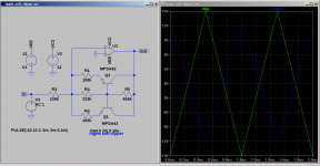
This is what LTspice shows. The result is what I expect when reading your circuit. Did I miss anything?
That is nothing like what I see on a real circuit with a scope.
I see a sine wave with rounded tops.
That is nothing like what I see on a real circuit with a scope.
I see a sine wave with rounded tops.
This may work within a small level range. But if you increase the level further, this acts as a gain -1x amp. Until output level limit is reached - ending in harsh clipping.
No, this is not a limiter.
This may work within a small level range. But if you increase the level further, this acts as a gain -1x amp. Until output level limit is reached - ending in harsh clipping.
No, this is not a limiter.
Not at all, it works very well with an amplified guitar signal.
I have used one since about 1980 with great results.
I picked up the circuit in a 1980's Wireless World readers circuits.
I think you are being misled by ltspice which isn't showing correct results for this circuit.
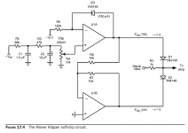
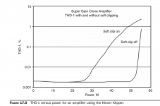
Klever Klipper circuit
Here is soft-clipping circuit from book "Designing Audio Power Amplifiers" by Bob Cordel.
Circuit should go before poweramp.
Mind you, that soft-clipping increases THD.
Here is soft-clipping circuit from book "Designing Audio Power Amplifiers" by Bob Cordel.
Circuit should go before poweramp.
Mind you, that soft-clipping increases THD.
Attachments
Last edited:
Not at all, it works very well with an amplified guitar signal.
I have used one since about 1980 with great results.
I picked up the circuit in a 1980's Wireless World readers circuits.
I think you are being misled by ltspice which isn't showing correct results for this circuit.
I think you never tried to understand that circuit and its limitations.
Output transformer emulation
Also part of the guitar tube power amplifier sound is output transformer. I think the easiest way to introduce transfomer distortion is to use one as driver for output transistors. This should require small transformer, thus keeping cost and weight low.
Some summary of very good SS guitar power amp needed features:
- soft-clipping - Klever klipper
- damping factor of one or less - mixed-mode feedback
- transformer distortion - small driver transformer
- little saggy power supply
I think you never tried to understand that circuit and its limitations.
It has no limitations in the real world it work amazingly well.
I think you never tried to understand that circuit and its limitations.
So why does the circuit work ok in my ltspice ?
http://www.ckpr.talktalk.net/softlimiter.asc
- Status
- This old topic is closed. If you want to reopen this topic, contact a moderator using the "Report Post" button.
- Home
- Live Sound
- Instruments and Amps
- Guitar amplifier project.