I am in the process of designing a complete guitar amplifier.
I have split it into 2 pcb's.
One pcb is a lateral mosfet power amplifier.
The other pcb is the pre amp and power supply.
I have bought a 5u high case for it. This will give plenty of room to space things out.
The heat sink is internal with a fan to keep things cool.
The controls are volume, treble, bass and master volume.
Reminds me of my amp that I designed in the early eighties.
A push-pull-stage with output transformer, current driven, feeds a 15" speaker. With a preceeding soft clipper based on OTA CA 3080. And the power transistors are a pair of BUZ11, still operating seamless after decades")
A push-pull-stage with output transformer, current driven, feeds a 15" speaker. With a preceeding soft clipper based on OTA CA 3080. And the power transistors are a pair of BUZ11, still operating seamless after decades
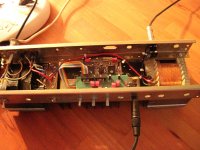
This is an actual picture of the amp. The output transformer on the right side contains a bifilar primary winding for the push-pull, but no secondary: The speaker is connected directly to the primary. This gives about 30W/8Ohm with 12V battery supply. The mains transformer delivers 24V= roughly, so there is enough power!
Attachments
Last edited:
Here is the soft limiter stage.
An externally hosted image should be here but it was not working when we last tested it.
Thanks Nigel, I have stashed that away for a future project.
I picked that circuit up in the 1980's from a Wireless World readers circuit.
It works good with plenty of treble boost.
I usually add a presence stage after it.
Cool
What sort of presence stage?
Just a treble boost.
I used one with a potentiometer and capacitor in an op-amp feedback loop.
Cool. Does the schematic survive?
In 2013 I rewired the power stage, but I was too lazy for a pcb-layout. At that time I did some documentation.
Attachments
Last edited:
Started building up the preamp/psu pcb.
An externally hosted image should be here but it was not working when we last tested it.
Last edited:
I finished the amplifier off today.
Lots of hole punching and drilling.
Measure twice and cut once !
Powered up amplifier and horror of all horrors a hum on the output !
I just connected audio once to smoothing capacitor zero volts but it still hums.
So had to cut ground from amp power supply to pre amp audio ground then connect audio ground straight to power amp input ground.
Now amp is silent with no audio signal.
I thought I understood ground loops but obviously not quite.
Another project and another lesson learnt.
I finished the amplifier off today.
I thought I understood ground loops but obviously not quite.
Another project and another lesson learnt.
Yes, we all understand ground loops. But sometimes we simply forget!
- Status
- This old topic is closed. If you want to reopen this topic, contact a moderator using the "Report Post" button.
- Home
- Live Sound
- Instruments and Amps
- Guitar amplifier project.