Fooboo
Sorry but after trawling some 84 pages of search results this is the best I can come up with .....
http://www.diyaudio.com/forums/showthread.php?postid=1505441#post1505441
I thought there was more info, but for the life in me I can't find it.
Possibly you could try for a more "newcomer friendly" clarification of the concerns and suitable values/components to control the offset in a seperate post.
John
Hi John
I've been trawling through pages and pages myself It's at once both edifying and confusing! But I am making some sort of progress. DD is a veritable feast of knowledge and is a great beginners guide. So with that in mind I am almost certainly going to go with the more 'complicated' version as it has the DC blocker in place so I feel more confident that no problems will be caused by source/amp mismatch. I am not going to worry about getting the 'highest quality' components at this time though I will obviously follow the material type's of each component IE. metal film, carbon, MKS, polystyrene, etc etc. Obviously as soon as I can get the parts (roll on Christmas) i can 'pose' them to get a better idea of the real layout and construction which will go a long way to assisting my understanding, Sadly I fear I am never going to understand half of the 'math' involved. I can do basic math but the implementation within electronics is stuck firmly at VIR. I had a horrendous maths teacher during secondary school and the damage he did to my confidence has screwed up any chance of me getting to grips with it. I am jealous as hell at all those who can seemingly 'magic' and use electronic formula as if it was their first language and there have been times when more than just my toys have been hurled from the pram because I can see and read the math, the explaination but lack that certain something to be able to then apply such information outside of the safety of the 'example'. If I ever see that teacher I am likely to commit villiany about his person! Still so long as I can find the answers thats fine, so long as I ask the right questions would be better
regards
Fooboo
I've been trawling through pages and pages myself
It's at once both edifying and confusing! But I am making some sort of progress. DD is a veritable feast of knowledge and is a great beginners guide. So with that in mind I am almost certainly going to go with the more 'complicated' version as it has the DC blocker in place so I feel more confident that no problems will be caused by source/amp mismatch. I am not going to worry about getting the 'highest quality' components at this time though I will obviously follow the material type's of each component IE. metal film, carbon, MKS, polystyrene, etc etc. Obviously as soon as I can get the parts (roll on Christmas) i can 'pose' them to get a better idea of the real layout and construction which will go a long way to assisting my understanding, Sadly I fear I am never going to understand half of the 'math' involved. I can do basic math but the implementation within electronics is stuck firmly at VIR. I had a horrendous maths teacher during secondary school and the damage he did to my confidence has screwed up any chance of me getting to grips with it. I am jealous as hell at all those who can seemingly 'magic' and use electronic formula as if it was their first language and there have been times when more than just my toys have been hurled from the pram because I can see and read the math, the explaination but lack that certain something to be able to then apply such information outside of the safety of the 'example'. If I ever see that teacher I am likely to commit villiany about his person! Still so long as I can find the answers thats fine, so long as I ask the right questions would be better regards
Fooboo
Fooboo
Don't forget that a university degree length study period would be a blink of an eye compared to the experience of many of the forum members. I would imagine some of them struggled with first steps as well in their early days.
For first builds I would say you are doing the right thing erring towards caution. If you know you are fine for DC blocking etc you can use whatever source you fancy and enjoy it without concern for your speakers.
Don't stress about exotic capacitors and the like until you are familiar with the sound of regular bits, there are enough varieties of chipamp to be going on with as it is, and soon (hopefully) there will be Nuuks unveiling too.
I've got a chipamp.com basic kit, an audiosector premium and a P2P using Farnell bits here. They all sound slightly different to each other, but I couldn't say I like one better than the others. They all sound better than anything I had owned before so what's not to like?
Have you found Cricklewood Electronics in your reading? They have a good range of bits.
http://www.cricklewoodelectronics.com/Cricklewood/home.php
I've also got a couple of teachers in my past who may have known their subject inside out, but couldn't pass it on to save their lives. Stick at it and prove him wrong.
John
Hi John
Aye cautionary is best I think . I am looking forward to building and listening to my own amp. My Shop bought HiFi has a graphic equaliser which was pretty much set to 'rock' So it will be intriguing to actually 'listen' to the music as it is rather than tweak it. Cricklewood are one of my mainstays I got my 30 odd TDA2003 chips from them and any components that are OS from rapidonline. There is Farnell as well but I haven't had reason to use them. Are there any other UK suppliers worth noting? Theres RS as well IIRC. Is Nuuk the DD website owner BTW? Thanks for the encouragement.......maybe drinking the blood of aforementioned teacher might help
regards
Fooboo
Aye cautionary is best I think
. I am looking forward to building and listening to my own amp. My Shop bought HiFi has a graphic equaliser which was pretty much set to 'rock' So it will be intriguing to actually 'listen' to the music as it is rather than tweak it. Cricklewood are one of my mainstays I got my 30 odd TDA2003 chips from them and any components that are OS from rapidonline. There is Farnell as well but I haven't had reason to use them. Are there any other UK suppliers worth noting? Theres RS as well IIRC. Is Nuuk the DD website owner BTW? Thanks for the encouragement.......maybe drinking the blood of aforementioned teacher might help regards
Fooboo
Aye Nuuk is Mr DD.
One of the joys of diy in whatever form are the people who fund bandwidth, share knowledge and offer designs that took time and effort on their part to develop and document. Then they give it away for free, I think it's a splendid thing to do.
Here is another take on point to point building. The most valuable lesson I got from it is to not rely on solder for mechanical strength and fixing.
http://www.mhennessy2.f9.co.uk/microamp/construction.htm
When I did my first P2P LM3875 I used too heavy a solid core copper wire on the + and - pins and for the power ground. By the time I have got enough heat on to solder to the copper wire it has desoldered from the chip pin and put too much heat into the chip to boot.
If I had wrapped the pins around and used lighter wire I could have avoided both problems and made the job easier for myself.
Buy yourself a big magnifying glass if you haven't already got one, the chip pins are close together and easy to accidentally bridge.
John
Hi Chaps, Mr Nuuk Sir, 'tugs forelock respectfully'
I have a set of helping hands complete with a magnifier. The hands have been really useful the glass however only gets used if the text on components is difficult to read. My only other tools of choice are daylight and a solid surface to work on. A halogen light is second choice. I am, it has to be said, a neat freak when it comes to electronics. On a PCB all the resistors are orientated the same way, as in the colour bands reading direction, Polyester caps similarly are positioned with the text orientated in a common direction. It's sad I know.
Thats another website bookmarked Cheers.
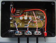
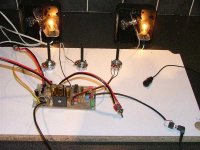
Heres a picture of my baby. This was my re-entry into electronics. Starting from a poorly photo copied schematic of a circuit known as the 'Vader Mod'. This was a Dick King Smith Kit now no longer available. I built it on breadboard to start then transfered it to vero board. The original circuit used a LM386 chip as a power amp so lacked the 'punch' it really needed for the specific use it is popular for. So I found the TDA2003 Data sheet complete with a PCB pattern. Thanks to the original illustrator I could see in the schematic of the vader mod where the power amp started and finished so I was able to dismantle that part of the circuit and simply slip the TDA amp in it's place. The vader mod is based on the original PCB pattern but has been edited to 'improve' it's layout with the rest of the circuit. The only part of the pattern I can take any real credit for is the sound to light part. But again this is down to who ever drew the schematic it was based on as it translated into a PCB pattern really well and I only had to worry about remembering to thicken the power in traces and the power to light traces. No audio design concerns here. During it's final testing an Australian member of the forum contacted DKS about the defunct kit and she secured 'permission' to use the design. So under the GPL type licence there is a 20 page manual of building instructions for the unit freely available to forum members. It covers everything from part selection/sources, pictorial assembly instructions, component identification and special notes therein. Also included is the PCB pattern and component silkscreen image for those who can etch their own (instructions on this are also in the manual) I have sold 30 kits/part builds/full house units. Other than it's simplicity it is a lot cheaper than any other ready built units. The idea was to have a freely available design that the 'common' man/woman could have ago at with a high chance of success. It took 18months to get it all sorted and I am now working on the MKIIIa which has a bridged amp for increased output over the 4W design. Heres one I built.
regards
Fooboo
I have a set of helping hands complete with a magnifier. The hands have been really useful the glass however only gets used if the text on components is difficult to read. My only other tools of choice are daylight and a solid surface to work on. A halogen light is second choice. I am, it has to be said, a neat freak when it comes to electronics. On a PCB all the resistors are orientated the same way, as in the colour bands reading direction, Polyester caps similarly are positioned with the text orientated in a common direction. It's sad I know.
Thats another website bookmarked
Cheers.Heres a picture of my baby. This was my re-entry into electronics. Starting from a poorly photo copied schematic of a circuit known as the 'Vader Mod'. This was a Dick King Smith Kit now no longer available. I built it on breadboard to start then transfered it to vero board. The original circuit used a LM386 chip as a power amp so lacked the 'punch' it really needed for the specific use it is popular for. So I found the TDA2003 Data sheet complete with a PCB pattern. Thanks to the original illustrator I could see in the schematic of the vader mod where the power amp started and finished so I was able to dismantle that part of the circuit and simply slip the TDA amp in it's place. The vader mod is based on the original PCB pattern but has been edited to 'improve' it's layout with the rest of the circuit. The only part of the pattern I can take any real credit for is the sound to light part. But again this is down to who ever drew the schematic it was based on as it translated into a PCB pattern really well and I only had to worry about remembering to thicken the power in traces and the power to light traces. No audio design concerns here
. During it's final testing an Australian member of the forum contacted DKS about the defunct kit and she secured 'permission' to use the design. So under the GPL type licence there is a 20 page manual of building instructions for the unit freely available to forum members. It covers everything from part selection/sources, pictorial assembly instructions, component identification and special notes therein. Also included is the PCB pattern and component silkscreen image for those who can etch their own (instructions on this are also in the manual) I have sold 30 kits/part builds/full house units. Other than it's simplicity it is a lot cheaper than any other ready built units. The idea was to have a freely available design that the 'common' man/woman could have ago at with a high chance of success. It took 18months to get it all sorted and I am now working on the MKIIIa which has a bridged amp for increased output over the 4W design. Heres one I built.regards
Fooboo
Attachments
Tut shame on you! Give up? OK...........
It's a voice modulator with sound to light and a TDA2003 amplifier.
Basically you speak into the Mic and something akin to a Dalek
voice comes out the other end and the lights flash in sympathy
to the vocal output as per the BBC prop The pots control the
light sensitivity, volume and modulation rate. Theres a few full
size home built props with my unit in them
regards
Fooboo (also building a full size Dalek )
It's a voice modulator with sound to light and a TDA2003 amplifier.
Basically you speak into the Mic and something akin to a Dalek
voice comes out the other end and the lights flash in sympathy
to the vocal output as per the BBC prop
The pots control thelight sensitivity, volume and modulation rate. Theres a few full
size home built props with my unit in them
regards
Fooboo (also building a full size Dalek
)john blackburn said:Make sure you know if you have the T or TF chips. I ordered LM3875Ts (uninsulated) and then found out the price of silpads, it cost twice as much for the insulating pads than the cost of the chips.
Hi John! I also mistakenly purchased the "T" version. Then there was the month I spent trying to purchase Mica in that size. That didn't work. But, I still wanted to use my LM3875's for parallel amplifiers. Fortunately, just before trying to find and shave the mica rocks myself, I heard of Kapton. So, I bought a roll of it.
(also building a full size Dalek )
Good show! The world needs more Daleks as far as I am concerned. I've never heard the manic pepper pot description before.
We have a big Varian DS202 vacuum pump that might be up for sale if you know anyone that's into doing their own vac forming or lots of veneering. Pictures and details can be sorted out if anyone is interested. We bought it to de gas casting plaster, and then stopped casting stuff.
It would be strictly buyer collects or pays the freight though as it's extremely heavy. There are couplings, relief and control valves, hoses and a small vac chamber included, it can be seen working in all it's bubble wrap destroying glory.
John
PS show us your dalek.
Hi All
Oh yes I am! Early days yet for me though. I have one of the harder parts to self build, the dome (taken from an original mold), the tubing for the appendages (eye stalk, plunger, and blaster including a pair of stainless steel 4" garden globes that make the ball joints for the arm and blaster) I have made the eye using a magic 8 ball carefully cut in 2 places then a baked bean tin is added and P38 filler (bondo) to blend the parts. Today I got one of the hardest parts to find for the particular Dalek type I am building (A Genesis) which is a pair of 1961-67 landrover side light lenses for the ear lights! The rest of it is just MDF, plywood, fiber glass. www.projectdalek.com to see some fine examples of new and old builds.
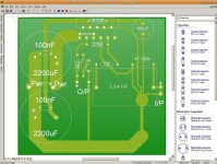
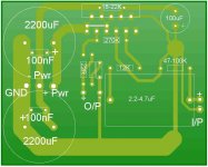
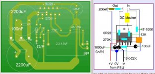
Any hoo I have been fiddling with my PCB software practicing making PCB patterns. This one is based on Nuuk's 3886GC circuit, as a mono only. I have tried to do it based on the 'rules' about signal earth's, power earth's and trying to keep distances down soooo here it is and feel free to laugh or kick my behind. Basically will the layout work? The 2 unmarked components in the middle are the resistor and cap that form the Zobel network the large rectangle is the DC blocker (a polystyrene cap) and the 2200uF caps are as per carlosFM's PSU suggestion including the 100nF caps which will be fitted on the track side of the pattern. If it is correct I can see it can be compressed vertically.
regards
Fooboo
Oh yes I am!
Early days yet for me though. I have one of the harder parts to self build, the dome (taken from an original mold), the tubing for the appendages (eye stalk, plunger, and blaster including a pair of stainless steel 4" garden globes that make the ball joints for the arm and blaster) I have made the eye using a magic 8 ball carefully cut in 2 places then a baked bean tin is added and P38 filler (bondo) to blend the parts. Today I got one of the hardest parts to find for the particular Dalek type I am building (A Genesis) which is a pair of 1961-67 landrover side light lenses for the ear lights! The rest of it is just MDF, plywood, fiber glass. www.projectdalek.com to see some fine examples of new and old builds. Any hoo I have been fiddling with my PCB software practicing making PCB patterns. This one is based on Nuuk's 3886GC circuit, as a mono only. I have tried to do it based on the 'rules' about signal earth's, power earth's and trying to keep distances down soooo here it is and feel free to laugh or kick my behind. Basically will the layout work? The 2 unmarked components in the middle are the resistor and cap that form the Zobel network the large rectangle is the DC blocker (a polystyrene cap) and the 2200uF caps are as per carlosFM's PSU suggestion including the 100nF caps which will be fitted on the track side of the pattern. If it is correct I can see it can be compressed vertically.
regards
Fooboo
Attachments
Heres a picture of the Dark dimensions special weapons Dalek.
The guy on the left is a CGI artist par excellence! He Developed
a 3D image from the original 2D art work and added his own spin
into the mix. The Guy on the right built the full size from the CGI
drawings. It is fully motorised, voice mod, and water pistols of
90PSI enjoy
The guy on the left is a CGI artist par excellence! He Developed
a 3D image from the original 2D art work and added his own spin
into the mix. The Guy on the right built the full size from the CGI
drawings. It is fully motorised, voice mod, and water pistols of
90PSI
enjoyAttachments

These 3 were also at the same trundle the first is a New series Dalek (NSD)
the second is a Resurrection Dalek 1980's (peter davidson era) the third is a
Circa 1960's type. Dalek invasion of earth (Hartnell's era) I operated the NSD
for most of the day...........yes it's fun Incidently in the last 2 episodes of
Dr Who one of our project dalek members had his dalek 'borrowed' by the BBC
as they needed four 'hero' props rather than just their own 3.
regards
Fooboo
the second is a Resurrection Dalek 1980's (peter davidson era) the third is a
Circa 1960's type. Dalek invasion of earth (Hartnell's era) I operated the NSD
for most of the day...........yes it's fun
Incidently in the last 2 episodes ofDr Who one of our project dalek members had his dalek 'borrowed' by the BBC
as they needed four 'hero' props rather than just their own 3.
regards
Fooboo
Attachments

Edit I missed the last post
Nice work on the Dalek front! Is that the collective noun then? a trundle of Daleks. It fits nicely.
As far as the PCB goes I would say the lower 2200 cap is wrong, in that there is no power supplied to the negative rail.
You need a positive rail, a negative rail and a power ground (usually between the "non rail" pins of the capacitors) The 100nf capacitor only gives a path to ground for stray AC (and maybe RF). It will allow AC to pass through it but block DC in it's tracks. (An inductor does the opposite as I understand it, allowing DC to pass but blocking AC)
If you look at the board for a Chipamp.com amp,
http://www.chipamp.com/lm3886.shtml
The amp pcb is divided into 3 sections. One end is V+, the other end is V- and the area between the caps is power ground and speaker return.
If you took your speaker return and power grounds to the point you have marked as -PWR and fed your V- to the negative pin of the lower cap I think it would be nearer. There may be things I haven't spotted in the rest, I'm not familiar with the 3886 layout.
I'm struggling to describe this so hopefully someone can give a more concise description.
It still doesn't look right to my untrained eye.
Draw yourself 2 caps with + and - opposed. Draw a line from + on one to - on the other. The centre of that line is your power ground and speaker return point.
Draw a line from the unconnected positive pin to the + chip supply. Do the same with the unconnected negative to the - chip supply.
These lines are your V+ in and V- in points.
With a split supply your rectifier DC outs are tied together, the negative of one being tied to the positive of the other at the power ground between the caps. This means when referenced to your power ground you have "X" volts positive to ground, and "X" volts negative to ground rather than just a positive and ground single supply.
Got to dive out now for a couple of hours and sorry if I'm teaching my Granny to suck eggs. If not, I hope it helps.
- Status
- This old topic is closed. If you want to reopen this topic, contact a moderator using the "Report Post" button.
- Home
- Amplifiers
- Chip Amps
- Guidance for a 'beginner'