This is the correct way to wire up a two channel amplifier.
But, it does not work!
There are tricks that improve it, but I have found none that make it as good as an uncased monoblock, where it is relatively easy to achieve <0.1mVac and <0.1mVdc at the output of the amplifier. (effectively <=50uVac 1kHz bandwidth and <50uVdc when using a DMM)
The monoblock works, but, as soon as you build in stereo it induces susceptibility to noise. Connect a pair of interconnects from a stereo source and you get an unwanted loop.
I am following Jneutron's thread avidly in the hope that he is going to guide me through the intricacies of electrostatic and electromagnetic fields and all the other paraphernalia that we need to know to fully understand correct grounding and how current flows and maybe why it flows the unexpected way inducing noise as it does so.
common definitions
Monoblock = a single channel with it's own case and PSU and connection to mains
Dual Channel (pseudo) monoblock = two channels each with their own PSU, transformer, and separate Audio Ground, but a shared case and usually a shared connection to mains.
Two channel = two channels each with their own PSU and Audio Ground, but shared transformer with isolated secondaries for each channel, shared case and mains connection.
Two channel = two channels each with their own PSU but sharing Audio Ground and Case and mains connections.
Two channel and most multi-channel = shared PSU, Audio Ground, case and mains connection.
Although more expensive, the monoblock performs better than any of the others. Note the variety of Two Channel amps.
Hi Andrew
") Well I understood that! So I must be getting somewhere. I have seen an example, on here, where an open ended interconnect shield assists in shielding but because only one end is wired to the circuit (amp end?) it stops the ground loop theoretically. I had a similar situation whilst developing my voice mod with sound to light. The original version had a mic for the voice circuit and a mic for the sound to light circuit. They where independent circuits but could be combined but as the were then joined at the battery in parallel the mic was connected thus; A single core shielded cable connecting the electret mic to Gnd and in, the sound to light was connected via a single core audio cable in parallel at the mic end but only the signal wire was fitted to the sound to light circuit (in) to prevent ground looping or stopped the spike in the sound to light circuit, when the filament bulbs fired up, from introducing any extraneous noise via the input. Any way I had a feeling that mono block was likely to be the answer for the beginner. More expensive as you say but allows the realisation of your working amp without the complications of ground looping worries. So I will build a dual PSU system I think, it will save the worry for now . So with the circuit layout done (largely by your good self) and understanding how to wire it up, and to go 'psuedo' monoblock I am good to go???
Well I understood that! So I must be getting somewhere. I have seen an example, on here, where an open ended interconnect shield assists in shielding but because only one end is wired to the circuit (amp end?) it stops the ground loop theoretically. I had a similar situation whilst developing my voice mod with sound to light. The original version had a mic for the voice circuit and a mic for the sound to light circuit. They where independent circuits but could be combined but as the were then joined at the battery in parallel the mic was connected thus; A single core shielded cable connecting the electret mic to Gnd and in, the sound to light was connected via a single core audio cable in parallel at the mic end but only the signal wire was fitted to the sound to light circuit (in) to prevent ground looping or stopped the spike in the sound to light circuit, when the filament bulbs fired up, from introducing any extraneous noise via the input. Any way I had a feeling that mono block was likely to be the answer for the beginner. More expensive as you say but allows the realisation of your working amp without the complications of ground looping worries. So I will build a dual PSU system I think, it will save the worry for now . So with the circuit layout done (largely by your good self) and understanding how to wire it up, and to go 'psuedo' monoblock I am good to go???
If a psuedo mono block has separate AG but shares a common case Wont the case link the 2 separate AG's? The answer is yes but the line of least resistance is via the wiring so it doesn't cause a problem??
regards
Fooboo
Well I understood that! So I must be getting somewhere. I have seen an example, on here, where an open ended interconnect shield assists in shielding but because only one end is wired to the circuit (amp end?) it stops the ground loop theoretically. I had a similar situation whilst developing my voice mod with sound to light. The original version had a mic for the voice circuit and a mic for the sound to light circuit. They where independent circuits but could be combined but as the were then joined at the battery in parallel the mic was connected thus; A single core shielded cable connecting the electret mic to Gnd and in, the sound to light was connected via a single core audio cable in parallel at the mic end but only the signal wire was fitted to the sound to light circuit (in) to prevent ground looping or stopped the spike in the sound to light circuit, when the filament bulbs fired up, from introducing any extraneous noise via the input. Any way I had a feeling that mono block was likely to be the answer for the beginner. More expensive as you say but allows the realisation of your working amp without the complications of ground looping worries. So I will build a dual PSU system I think, it will save the worry for now . So with the circuit layout done (largely by your good self) and understanding how to wire it up, and to go 'psuedo' monoblock I am good to go???If a psuedo mono block has separate AG but shares a common case Wont the case link the 2 separate AG's? The answer is yes but the line of least resistance is via the wiring so it doesn't cause a problem??
regards
Fooboo
Hi There
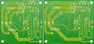
Tweaked the layout to allow the fitting of the 100nF and 3.3uF Caps on the component side. I think if I am careful I may be able to rotate and place the components to the right of the zobel trio and shrink the PCB without degrading the 'audio' requirements of the layout. What do you think so far?
regards
Fooboo
Attachments
Hi there.
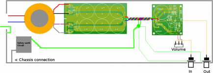
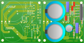
Well here's a pic of the full wire up including the volume control. I believe this is referred to as a monoblock? I intend to build 2 in a single case and use a ganged pot for volume control. I also fiddled with the layout a bit so everything is on the top side of the PCB the board is around 2" square. The PSU will be built on perf board and single core mains copper wire used as the linkage for everything. Fingers crossed I have understood everything so far (Thanks for the considerable help) and I can build, test, and run the Amp with minimal problems.
Regards
Fooboo
Attachments
Hi Fooboo, hope all went well for your journeys over the holiday.
A mate is having a Christmas party but owing to his rather "relaxed" lifestyle, it's not until the 24th of January.
This means that I should be over in Yorkshire again around that weekend if you fancy a second shot at hearing a chipamp.
How are you getting on with your parts gathering? Santa brought me tokens for a transformer and some diodes. Makes your stockings a funny shape, but far more welcome than aftershave and socks.
I've got socks that date back to the age of steam, I don't need any more just yet.
John
But may I humbly suggest that you start off with some homework by visiting the Gainclone pages
Thanks man that site has good building and safety tips for beginners.
- Status
- This old topic is closed. If you want to reopen this topic, contact a moderator using the "Report Post" button.
- Home
- Amplifiers
- Chip Amps
- Guidance for a 'beginner'