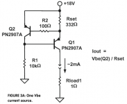
Depends. Schematic? The CCS I used was a cascode bipolar.
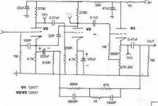
The schematic is attached below, the current is a little less than your measurement subject I think, TP1 is 140V so current is (250-140)/270k = 0.41mA
Not sure what a cascode bipolar looks like TBH, every time I look on the internet I get a different toplogy, some with diodes, some with leds here, leds there, the odd potentiometer etc. Very very confusing. I've attached a picture of what I think a Bipolar cascode current source is (from Walt Jung's paper), but like I say, it could be anything

I think I understand why people use a resistor
Attachments
Probably not suitable for that design.
The bipolar CCS I used was a diyAudio group project; I think Greg the Geek was selling boards and documentation for it; it's pretty similar to the designs shown in Morgan Jones's book (though without the misprint, harrumph). The one you showed is actually a ring of two rather than a cascode.
The bipolar CCS I used was a diyAudio group project; I think Greg the Geek was selling boards and documentation for it; it's pretty similar to the designs shown in Morgan Jones's book (though without the misprint, harrumph). The one you showed is actually a ring of two rather than a cascode.
Hehehe, I knew it would be something sneaky right under our noses
It could be one of many tubes, that's why I've asked about V/A curves.
The schematic is attached below, the current is a little less than your measurement subject I think, TP1 is 140V so current is (250-140)/270k = 0.41mA
You can use LED and CCS with V2 since it is loaded on a high resistance bootstrapped input.
Last edited:
Not sure what a cascode bipolar looks like TBH, every time I look on the internet I get a different toplogy
There was a good document somewhere on this forum called
diyAudio-CCS-beta2.pdf
Or an alternative way from Geek: http://www.classicvalve.ca/docs/CVD_CCS_preliminary_docs.pdf
The particular spectrum I showed was a smooth plate Telefunken. I also tested some small plate eastern European tubes (several brands, all clearly from the same factory). 5 tubes in all (2 Telefunken, 3 small plate), 10 sections, pretty similar results. Haven't tested a JJ, but I have one so I should.
The particular spectrum I showed was a smooth plate Telefunken. I also tested some small plate eastern European tubes (several brands, all clearly from the same factory). 5 tubes in all (2 Telefunken, 3 small plate), 10 sections, pretty similar results. Haven't tested a JJ, but I have one so I should.
Thanks, though I thought I was done hearing about smooth plate Telefunken.
John
Not sure what a cascode bipolar looks like TBH, every time I look on the internet I get a different toplogy,
Glubulator (...and a thousand lurkers...), for a practical example see post #5 from Mr. tubelab in this thread: http://www.diyaudio.com/forums/tubes-valves/61175-parafeed-resistive-load.html
: )
Not sure what a cascode bipolar looks like TBH, every time I look on the internet I get a different toplogy,
(OK, so I'm bored, so...)
Post #25 in this thread: http://www.diyaudio.com/forums/tubes-valves/63652-mosfet-current-source-triode-load-3.html
... time for breakfast.
Ok, guess what is it, if I don't tell about Volt / Ampere characteristics (in this particular case, size of the flower)?
Tip: it's from my garden.
Tip: it's from my garden.
An externally hosted image should be here but it was not working when we last tested it.
Very high. VERY high. 10M, 10pF.
The particular spectrum I showed was a smooth plate Telefunken.
I'd hope the $100 tube into a near infinite load measured well. The real test is the JJ into a 250K load.
....funny thing about 6SL7...
Distortion spectra or it didn't happen.
I'd hope the $100 tube into a near infinite load measured well. The real test is the JJ into a 250K load.
A 250k load is much too low for good performance from this tube- that was one of the points I was trying to make. Most 12AX7 circuits are sub-optimal.
FWIW, the spectra from the cheap eastern European tubes (some bought at Radio Shack!) were pretty much the same as the Telefunken; I just happened to have the Telefunken curves handy. Based on what I saw from the JJ ECC81, I wouldn't be surprised if their ECC83 performed even better.
If I had gotten to this thread earlier, I would've guessed a 1L6. But I guess there probably aren't too many Zenith TransOceanic owners on here, are there?
I have two, both work fine.
Ok, guess what is it, if I don't tell about Volt / Ampere characteristics Tip: it's from my garden.
OK, I have a power supply, a current meter and some clip leads. I have some doubts about the linearity though.
Ok, guess what is it, if I don't tell about Volt / Ampere characteristics (in this particular case, size of the flower)?
I sense a duel; pistils at dawn.
- Status
- This old topic is closed. If you want to reopen this topic, contact a moderator using the "Report Post" button.
- Home
- Amplifiers
- Tubes / Valves
- Guess That Tube