For some DIY audio enthusiasts, the thought of having an amplifier fail and blow their speakers is a persistent worry. After all, speakers can be rather expensive and mistakes do happen. However, any circuit added to the output of the amplifier should preserve the high quality of the output signal, which is no small feat. I designed the Guardian-86 and Guardian-686 to accomplish this goal.
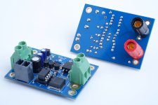
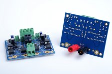
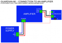
The Guardian-86 is intended for use with single-ended amplifiers, including discrete designs and the many LM3886-based amplifiers.
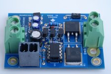
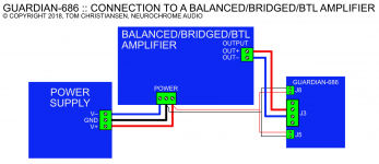
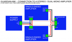
The Guardian-686 is mainly intended for use in bridged/balanced/BTL amplifiers. The Guardian-686 can also be used in stereo and dual-mono single-ended amplifiers.
For single-ended amplifiers (where one speaker terminal is connected to ground), one Guardian-86 is needed per channel. Two Guardian-86es or one Guardian-686 for a stereo or dual-mono single-ended amp.
Bridged/balanced/BTL amplifiers (where both speaker channels are driven) need one Guardian-686 per channel.
Both circuits protect the speaker against excessive DC voltage. They also provide a turn-on delay and immediate turn-off when the supply voltage drops below a set threshold to prevent those annoying turn on/off thumps.
The key features of the Guardian-86 and Guardian-686 are:
The other reason is that relays add measurable distortion, especially as they wear. MOSFETs provide much better and much more consistent performance throughout the lifetime of the MOSFET.
To read more about the Guardian-86 and purchase yours, follow this link: Guardian-86: Speaker protection board for LM3886-based amplifiers (and others).
For more information regarding the Guardian-686 and to purchase yours, click here: Guardian-686: Speaker protection board for balanced, bridged, and BTL LM3886-based amplifiers (and others).
I launched the Guardian-86 on May 31st and am almost out of boards. There are five left in the stack. I'll have more arriving in about two weeks.
I have a pretty tall stack of Guardian-686 boards in stock as it launched in the middle of July and I had more boards made.
Tom
The Guardian-86 is intended for use with single-ended amplifiers, including discrete designs and the many LM3886-based amplifiers.
The Guardian-686 is mainly intended for use in bridged/balanced/BTL amplifiers. The Guardian-686 can also be used in stereo and dual-mono single-ended amplifiers.
For single-ended amplifiers (where one speaker terminal is connected to ground), one Guardian-86 is needed per channel. Two Guardian-86es or one Guardian-686 for a stereo or dual-mono single-ended amp.
Bridged/balanced/BTL amplifiers (where both speaker channels are driven) need one Guardian-686 per channel.
Both circuits protect the speaker against excessive DC voltage. They also provide a turn-on delay and immediate turn-off when the supply voltage drops below a set threshold to prevent those annoying turn on/off thumps.
The key features of the Guardian-86 and Guardian-686 are:
- No relays! All switching is done with MOSFETs for the lowest distortion.
- No relay contacts to wear, thus, no change in performance due to aging.
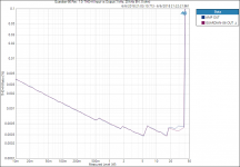
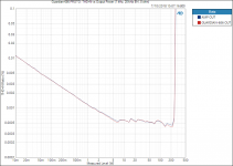
- No impact on sound quality. No measurable impact on distortion for the Guardian-86 and only negligible impact for the Guardian-686.
- Floating photovoltaic MOSFET driver ensures consistent good performance throughout the full swing of the output signal.
- Approx. 5-second delay on power-up. Output disabled when supply voltage falls below 22 V. This dropout voltage can be further optimized for your specific application by changing one zener diode.
- Input: Molex Mega-Fit connectors and terminal blocks accepting up to AWG 10 (5.2 mm2) wire.
- Output: Terminal blocks accepting up to AWG 10 (5.2 mm2) wire and 4.2 mm diameter holes at 3/4" (19 mm) pitch for direct mounting onto the speaker output terminals.
- With the exception of two huge surface mounted MOSFETs, all components are leaded.
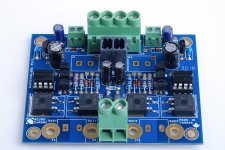
- Compact layout. The assembled board is approximately 1.05 inch (27 mm) in height. The Guardian-86 measures 2.50 x 1.75 inches. The Guardian-686 is a bit larger at 2.50 x 3.25 inches.
- Gold plated circuit board. Designed and manufactured in Canada. All boards are electrically tested before they leave the factory.
The other reason is that relays add measurable distortion, especially as they wear. MOSFETs provide much better and much more consistent performance throughout the lifetime of the MOSFET.
To read more about the Guardian-86 and purchase yours, follow this link: Guardian-86: Speaker protection board for LM3886-based amplifiers (and others).
For more information regarding the Guardian-686 and to purchase yours, click here: Guardian-686: Speaker protection board for balanced, bridged, and BTL LM3886-based amplifiers (and others).
I launched the Guardian-86 on May 31st and am almost out of boards. There are five left in the stack. I'll have more arriving in about two weeks.
I have a pretty tall stack of Guardian-686 boards in stock as it launched in the middle of July and I had more boards made.
Tom
Attachments
-
 Guardian-86_R1p0_ASSY_Pair.jpg729.8 KB · Views: 1,089
 -
 Guardian-86_R1p0_ASSY.jpg864.4 KB · Views: 1,106
 -
 Guardian-86 Rev. 1.0_ THD+N Input vs Output (1 kHz, 20 kHz BW, 8 ohm).png40.1 KB · Views: 1,070
 -
 Guardian-686_ASSY_Pair.jpg273.3 KB · Views: 1,030
 -
 Guardian-686_ASSY.jpg418.2 KB · Views: 1,028
 -
 Guardian-686 PROTO_ THD+N vs Output Power (1 kHz, 20 kHz BW, 8 ohm).png59.2 KB · Views: 584
 -
 Guardian-86_Connections.png66.4 KB · Views: 531
 -
 Guardian-686_ConnectionsBTL.png85.8 KB · Views: 565
 -
 Guardian-686_ConnectionsSE.png100.4 KB · Views: 586
Minimum 8 V. Maximum is set by how much power you can dissipate in a zener diode as well as the voltage rating of the MOSFETs. With the parts I've specified, I would not push it past ±50 V supply rails. If you swap out the MOSFETs and zener, you can push it higher.
The trip point where the output gets turned off is set by a zener diode. You can change it from about 5 V to 50 V by swapping the zener. Depending on how much ripple you have on your supply, I'd probably aim for 80 % of the nominal voltage as the trip point.
The Guardian-686 and -86 run from the same supply as the amp itself.
Tom
I haven't come across any grounding issues with the Guardian-86/686, so I question the necessity of a separate supply. However, if you wish to use a separate supply, I suggest getting a small 8-9 VAC transformer and fashion a small supply with a diode bridge and a 100 uF capacitor. Use that to feed the Guardian-86/686.
For this to work, you need to replace D4 in the Guardian-86 with a wire link. In the Guardian-686, it's D4 and D8 that need to be wire links with the ~8 V supply.
Tom
For this to work, you need to replace D4 in the Guardian-86 with a wire link. In the Guardian-686, it's D4 and D8 that need to be wire links with the ~8 V supply.
Tom
Tom,
Are these specific for only amplifiers designed for speakers or can one adapt them for headphones as well? One issue I see is that these have been designed to detect DC at 700mV or so and for headphones you would probably want to aim for 1/10th that value.
Thanks,
Anand.
Are these specific for only amplifiers designed for speakers or can one adapt them for headphones as well? One issue I see is that these have been designed to detect DC at 700mV or so and for headphones you would probably want to aim for 1/10th that value.
Thanks,
Anand.
The trigger voltage is fixed.
You don't necessarily need a lower trigger voltage in a headphone amp. The Guardian-86 would protect your headphones in cases of catastrophic amplifier failure where the amp ends up delivering the full rail voltage on its output. That would be the case if one of the output devices shorts to the supply rail.
Excessive DC offset is better dealt with by AC coupling or by using a DC servo.
Tom
The Guardian-86 and -686 only protect against DC voltage on the output of the amp. They do not limit the current to the speaker.
The Guardians also disconnect the speaker for the first few seconds after power-up and as soon as the supply voltage collapses below 75-80% of its nominal value on power-down. The power-down trip point can be customized by changing a zener diode.
Tom
The Guardians also disconnect the speaker for the first few seconds after power-up and as soon as the supply voltage collapses below 75-80% of its nominal value on power-down. The power-down trip point can be customized by changing a zener diode.
Tom
Last edited:
I am assuming this too. But in the given case I am talking about an existing amplifier that already has an output fuse (per left and right channel) and of course I would feel happy getting rid of it. Not sure now, whether the Guardian would do the trick or would rather suit as an add on to the existing fuse.
I'm generally not a fan of output fuses, but if the amp has one already and you're happy with the amp, I would keep the fuse.
If the amp has a current limiter built-in, you could go without the fuse. You would probably lose short-circuit protection, but you would have over-current protection for short-term overloads.
If the amp does not have a built-in current limiter, you'll need to add it to get that feature. Doing so could be pretty simple or pretty involved depending on the amp.
Tom
- Home
- Vendor's Bazaar
- Guardian-86 and Guardian-686: High-End Speaker Protection Circuits