I have a rather cool VU-meter with 60 dB dymanics, from 0.001 to 100 W. The speakers are Martin Logan SL3 electrostatic ones with not huge efficiency. The power amp itself can deliver around 200 watts/8 ohms.BrianGT said:
Let me reiterate my response here for others. I am using the LM3875 gainclone amplifier with my < 90 dB efficient Seas Thor TL speakers (I think they are around 87dB), and I get plenty of power with them. I can turn it up to the point where it makes my ears hurt, without the amplifier clipping.
When I have the TV on, 0.01-1 W is normal. 10 W is nearly party level. 100W the neighors complains. You must multiply the power with 10 in order to get a real change in sound level.
Peter Daniel said:What do you mean by clamp mounting? Since this board is minimalist approach, the size is also minimal, you can't move Zobel too far")
i call it clamp mounting for lack of better words. i know for a fact that you've done it even. a metal plate or bar is used to clamp the IC to the heatsink, thus ensureing no tilting of the IC. obviously the 4780 wouldn't require this feature unless you wanted to easily isolate the IC from the heatsink -- the metal tabs on the IC touch the default mounting points, thus requireing extra hardware or nylon screws. i guess some insulative material could be moulded there, but its not my suggestion that you would ever think that it was truely safe.
oh, that reminds me -- brian, in my experience with mininal sized boards with this chip, i found that mounting the caps isn't just about where they are on the board, but where they are with respect to the IC mounting points. on my board, with caps in place, it took 30 minutes to mount the ICs because i counld't get any tools into place to mount the chip. even now it is marginal, though the amp works fine.
It would have been probably easier to remove caps, mount the chip and then mount the caps again.
With this board, I checked into the proper access for installing the mounting hardware, so I think it shouldn't present a problem.
As to the components beyond the caps, if they are flat on the PCB, I don't see how they would prevent using the clamping bar. I understand you are talking about zobel parts, and in this case a resistor can be closer to chip and capacitor further away, so it won't be in a way.
I'm not using clamp anymore. I don't like it's influence on a sound.

Re: Waiting... Waiting...
I am still finalizing the details of the order, due the the recent discussions over the zobel network. I should have the revised board done soon, and will post pictures of it here.
--
Brian
jamesjung21 said:I'm sick of waiting for this group order to happen...
Brian & Peter Daniel, what's the current status of this group order?
I am still finalizing the details of the order, due the the recent discussions over the zobel network. I should have the revised board done soon, and will post pictures of it here.
--
Brian
Hey Brian-
Nice of you for being polite but don't let the pressure from one individual influence or compromise your work.
The majority appreciate the work and effort you have done.
If someone is in a hurry they can design/commission their own boards.
You are doing top notch work and offering phenomenal products virtually free. I can wait and be patient for that!
Thanks again for fabulous products,
Troy
ps- I'm eager for the new ones also, but I would never rush the design out of impatience.
Edit: spelling.
rabstg said:Nice of you for being polite but don't let the pressure from one individual influence or compromise your work.
The majority appreciate the work and effort you have done.
If someone is in a hurry they can design/commission their own boards.
You are doing top notch work and offering phenomenal products virtually free. I can wait and be patient for that!
Thanks again for fabulous products,
I am glad that you enjoy the products. I am not rushing the LM4780 boards. I am going to get prototypes made first, and try out the design.
I am actually anxious myself to get some boards in my hands to try out. The design has been looked over many times, and is almost ready for ordering prototypes.
There is also a revised LM3875 layout, which I will get made soon, as I am out of pcbs currently (all past orders have been fulfilled)
--
Brian
By the way, I see you(Brian) and Peter working allot on these together.
I don't want to exclude/ignore Peter’s VERY hard work but being somewhat new to this forum I don't know the working relationship between you two.
I have also come to respect and trust Peter's judgment quite quickly after seeing his work here too!
Thanks Peter!
Troy
I don't want to exclude/ignore Peter’s VERY hard work but being somewhat new to this forum I don't know the working relationship between you two.
I have also come to respect and trust Peter's judgment quite quickly after seeing his work here too!
Thanks Peter!
Troy
rabstg said:By the way, I see you(Brian) and Peter working allot on these together.
I don't want to exclude/ignore Peter’s VERY hard work but being somewhat new to this forum I don't know the working relationship between you two.
I have also come to respect and trust Peter's judgment quite quickly after seeing his work here too!
Thanks Peter!
Troy
Peter and I have been passing ideas back and forth for a few months with these designs. Before his input, I initially wanted to make a simple gainclone pcb, since I had a few friends who wanted gainclones, and I didn't want to wire them point-to-point for them. I showed him my initial pcb, and he helped me refine it into what it is now.
--
Brian
A member, who is modest enough (to pass Fred's scrutinity) sent me those pics, giving me permission to post them (in case I liked them). Well, it's a total opposite to what we try to achieve here, yet I find the layout and design quite interesting and carried out very well. It is a full implementation of LM4780, without any shortcuts taken.
Attachments
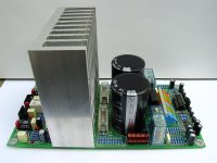
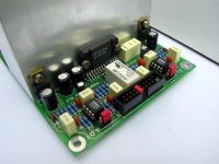
Very nice work indeed, Upupa Epops. 

You have used my "industrial" approach, using "normal" parts.
I especially like those Wago 256 connectors which creates the necessary pain (sharp springs into the wire) to the music, a real blues connector! I also like the nice looking coils, nice craftmanship.
You have used my "industrial" approach, using "normal" parts.
I especially like those Wago 256 connectors which creates the necessary pain (sharp springs into the wire) to the music, a real blues connector! I also like the nice looking coils, nice craftmanship.
Hey Peter-
In your post you stated the following:
"Well, it's a total opposite to what we try to achieve here"
May I ask you to throw out a few reasons for that statement?
Is it size, component type/brand, circuit layout....?
It does look stunningly meticulous, but also somewhat complicated. There are a lot of components on the board for a "chip amp".
Thanks in advance,
Troy
rabstg said:Hey Peter-
In your post you stated the following:
"Well, it's a total opposite to what we try to achieve here"
May I ask you to throw out a few reasons for that statement?
Is it size, component type/brand, circuit layout....?
It does look stunningly meticulous, but also somewhat complicated. There are a lot of components on the board for a "chip amp".
"Circuit is quite universal, you can connect it in all modes ( stereo, bridge, parallel and two modules as parallel / bridge for output power 200 W ). It has DC protection, delayed output and on input connector is taked + / - 15 V for prewiew stages ( electronic crossover, preamp etc. )"
The design that we try to finalise in this thread is aimed at minimalistic approach. That means only 1000u caps are used (as to me they sound better than 5,600 I tried already, and I wouldn't even dare to go with 22,000
). Also, we concentrate on basic implementation, so no stereo or bridged mode, just parallel. Stereo can be still achieved, but components have to be raised from the board.We use separate board for rectifiers, and we will provide the option to mount it piggy back style, directly attached to the amp's board. This reduces the size and allows more creativity with chassis design and most any style and chassis box can be used.
We also prefer to use more exotic components (as regretably over the months, they still prove to provide better sound than your military grade stuff) and direct connection of wires to the board. Although those fancy connectors look nice, direct solder joint certainly isn't any worse.
We not concentrate on fuses and output protection, leaving this option to end user. I also don't want to be limited by a heatsink choice as with this amps I prefer to use the chassis wall as heat disipating surface.
So basically the design philosophy is completely different, and I can't say that one is necessary better than other, it just brings different results
Re: Re: Waiting... Waiting...
Brian, what's the final conclusion of that zobel network discussion?
My suggestion of two paralleled 0.47 ohm resistors in series with the output?
BTW Peter sent me a board, very nice.
Thanks, Peter.
BrianGT said:
I am still finalizing the details of the order, due the the recent discussions over the zobel network. I should have the revised board done soon, and will post pictures of it here.
--
Brian
Brian, what's the final conclusion of that zobel network discussion?
My suggestion of two paralleled 0.47 ohm resistors in series with the output?
BTW Peter sent me a board, very nice.
Thanks, Peter.


- Status
- This old topic is closed. If you want to reopen this topic, contact a moderator using the "Report Post" button.
- Home
- Group Buys
- Group order of non-inverted LM4780 pc boards? Anyone interested?