I'm probably game for some boards as well.
Peter, I'm with you half way on the resistors, as there are some others I would like to try as well. I'm obviously not a savvy PCB layout designer, but it would be cool to have a board that accomodated various sizes of resistors (Caddocks, Vishays, Rikens, Holcos, etc.) the same as with the capacitors. While I gather from your previous posts you're a form-follows-function kind of guy, it does suck having some beautiful PCB's with resistors standing up on their ends! (Which I'm going to probably have to do with my other LM3875 boards since I have a bunch of other resistors I want to try!).
Is there any way to make the board slightly longer to accomodate bigger resistors? I don't know if space is limited on the size of the PCB (since it's probably going to be 1 board scored in 4 spots from the way I interpreted Brian's post), but I'm certainly willing to deal with a slightly larger board for the tweaking possibilities!! Hopefully this could be done without compromising the ground plane..
Jean said:Count me in for a pair of boards
Please sign up on the Wiki. I will try to finalize the board design by the end of the week and place the order.
Wiki:
http://www.diyaudio.com/wiki/index.php?page=LM4780+Eval+PCB+Group+Order
--
Brian
motherone said:I'm probably game for some boards as well.
Peter, I'm with you half way on the resistors, as there are some others I would like to try as well. I'm obviously not a savvy PCB layout designer, but it would be cool to have a board that accomodated various sizes of resistors (Caddocks, Vishays, Rikens, Holcos, etc.) the same as with the capacitors. While I gather from your previous posts you're a form-follows-function kind of guy, it does suck having some beautiful PCB's with resistors standing up on their ends! (Which I'm going to probably have to do with my other LM3875 boards since I have a bunch of other resistors I want to try!).
Is there any way to make the board slightly longer to accomodate bigger resistors? I don't know if space is limited on the size of the PCB (since it's probably going to be 1 board scored in 4 spots from the way I interpreted Brian's post), but I'm certainly willing to deal with a slightly larger board for the tweaking possibilities!! Hopefully this could be done without compromising the ground plane..
Just to see 2 horizontally mounted resistors, you would like to compromise the whole design?
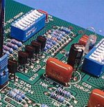
Look at this Pass Ono board. They have standing capacitors, so what's wrong with standing resistors?
Attachments
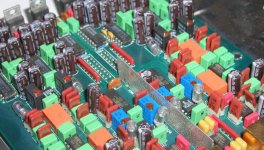
Now check this tightly packed Levinson board. Although some of those polystyrene caps are mounted horizontally, whenever space was limited, they mounted them in vertical position. I really don't know why people think that this way of mounting components is compromised? It all depends how it fits in a circuit, but I'd rather compromise placement of 2 components than other, more important aspects of the design. I wouldn't go with bigger board just to accomodate 2 resistors (which you propbably won't be using anyway).
Attachments
kestrel200 said:So..to have a bridged 150watt RMS Stereo I'd need two kits??
This is correct.
--
Brian

Brian:
Will you have documentation like last time? With pictures? This is especially helpful for real Dumas's.
Mr. Dumass has a question. What's the difference between parallelled and bridged designs? Get technical with me.
Pictures work.
By the way, my little billet clone is simply wonderful. I am piping XM through it to my line arrays. It's magic. I am very happy with the whole project and was very impressed by your preparation of the kits and the docs. OUTSTANDING
My AKSAs have some vertically placed resistors and I have never heard a bad word about them. I guess vertical resistors allows for a more compact and elegant PCB.
I could start a new theory that using vertical and horizontal resistors mean that the electrical and magnetical fields are at 90 degrees to one anther and therefore reduce the chance of cross talk.
I could start a new theory that using vertical and horizontal resistors mean that the electrical and magnetical fields are at 90 degrees to one anther and therefore reduce the chance of cross talk.
Just a quick question. Earlier in the thread Peter had a diagram with 2 boards facing each other and mentioned the 2 boards would have mirror image power connectors so you could simplify bridging 2 boards like this. Is it going to be done that way in the final version? it would be quite handy.
Are there sockets under some caps on Levinson's board? And if so I would they do such a thing? Upgrade?Peter Daniel said:Now check this tightly packed Levinson board. Although some of those polystyrene caps are mounted horizontally, whenever space was limited, they mounted them in vertical position. I really don't know why people think that this way of mounting components is compromised? It all depends how it fits in a circuit, but I'd rather compromise placement of 2 components than other, more important aspects of the design. I wouldn't go with bigger board just to accomodate 2 resistors (which you propbably won't be using anyway).
Brain, I'm sorry to say but this green trace is doing no good at all. I had also such ideas when I was younger but those traces are just antennas.mhennessy said:I couldn't resist improving the signal earthing further (possible alternative route shown in green, although I prefer the blue)
Check also my grounding, green.
Attachments
![pcb-layout[1].gif](/community/data/attachments/2/2495-cbaceca89c5e986998801dc15dd53f1b.jpg)
sunil said:Hello,
Could somebody please put in plain simple words what kind of real world output is possible using one board (single chip used in stereo) into 8 & 4ohms, and, 2 boards (two chips, bridged-parallel) into 8 & 4 ohms.
Thankyou,
sunil
I guess the reason why this hasn't been done is because it's difficult to predict or guarantee a particular output when variables like the power supply transformer are beyond National, Brian and Peters control. That's why, in a previous post, I explained my working and assumptions. Also, the PCB is not configured for stereo operation (you could mod it, but you'd be better off using one PCB for each channel). But, I would guess the following:
Single board:
8ohms - 60W
4ohm - 100W
Two boards bridged:
8 ohms - 150-170W
4 ohms - 200-250W
Technical bit:
Assumptions: Supply rails +/-40V, falling to +/-35V under load. Note that they might fall more, depending on capacitor value and transformer rating - hence the vagueness of the bridged results.
Assumed around 5V dropout in the IC's, meaning peak voltage swing is 30V, which is around 21V RMS (I also assumed this would vary with load as well). Note that in theory, you should get 4 times the output power when you bridge, but the losses compound, and you normally only get around twice the output. The parallel operation of each amplifier helps, but you still won't get better than 3 times in practice.
To get 40V rails, you'd need 28V secondaries. 30V secondaries would probably result in rails that are too high off-load (check the datasheet). Transformers with 25V secondaries are more readily available - but I would expect the outputs reduce to around 40, 75, 140 and 200W respectively.
As I said above, this stuff is hard to predict, and manufacturers will normally have to experiment with different transformers to arrive at the exact result they're after. So, until we start building and measuring, I wouldn't like to be any more specific
Note that these are RMS figures - under transient conditions, peak outputs will be higher. Heatsinking is very important at these power levels!
peranders said:
Brain, I'm sorry to say but this green trace is doing no good at all. I had also such ideas when I was younger but those traces are just antennas.
Check also my grounding, green.
Hi Peranders,
I wonder if you thought I was suggesting adding these traces along with the existing blue trace? Just to clarify, I was suggesting alternatives - I only intended Brian to use one path. More than one would create loops, which is bad (as you say). Sorry if it wasn't explicit in the origional post (although re-reading the bit you quoted, I think it was fairly clear)
Cheers,
Mark
Peter Daniel said:If you check pin out on the chip, the pin where you connected blue trace is NC. The best connection point for ground path would be your left, green trace.
Thanks - I hadn't noticed this - but National board connects these NC pins to ground, which is what Brian had done, so there's probably no real need to worry about this
Peter Daniel said:Regarding long traces from input resistors to the chip, I might be concerned with them, but obviously it wasn't a concern of National design team when they made evaluation board. Those traces are even longer on their board.
BrianGT said:Here is a picture of the National Evaluation board layout, for comparison purposes.
Would the output track where Rf2 connects be considered a T track?
I think that we're all in agreement (from here, and the previous thread about this board) that Nationals board is not an example of an optimised layout
Yours and Brians however, is
Cheers,
Mark
Peter Daniel said:Now check this tightly packed Levinson board. Although some of those polystyrene caps are mounted horizontally, whenever space was limited, they mounted them in vertical position. I really don't know why people think that this way of mounting components is compromised? It all depends how it fits in a circuit, but I'd rather compromise placement of 2 components than other, more important aspects of the design. I wouldn't go with bigger board just to accomodate 2 resistors (which you propbably won't be using anyway).
Hi Peter,
I think that mounting resistors vertically in your PCB is fine, and a useful compromise because it contributes to the overall small size. But, just for info, here are the objections to them
Increased suscecptability to RF pickup - this can be very serious in some applications. The problem is caused by having a conductor at right-angles to the ground-plane, which forms a good little antenna
Reduced reliability. Sounds unlikely, but think about how stuff gets serviced. When routing around inside a piece of kit, it's easy for these components to be knocked over so that they touch adjacent conductors. To get around this, some manufacturers use special, pre-formed resistors that have the exposed wire covered in the same enamal as the resistor body (you've probably seen these in el-cheapo kit)
Mechanical stability. For larger components that run hot, there's a greater chance of bad solder joints appearing because the mechanical stress on the joints is greater.
There's probably others as well, but it's still early in the morning for me
Just to finish with some (hopefully) sensible advice, when mounting components vertically, you can avoid some of the issues by deciding which way round to place the component. In the ML example above, I wouldn't mind betting that the long exposed wire was connected to ground, or failing that, the lowest impedance (or "earthy") part of the circuit.
So, for any resistor in your PCB, you can work out the optimum way to vertically mount all of the components, by just thinking about circuit impedances. For example, R4 should have the long lead connected to ground. The long wire of R2 should go to in the IC output node, as the input end of that resistor will be very prone to pickup.
Hope this makes sense and helps,
Mark
- Status
- This old topic is closed. If you want to reopen this topic, contact a moderator using the "Report Post" button.
- Home
- Group Buys
- Group order of non-inverted LM4780 pc boards? Anyone interested?