In the past it was very common to use the chassis as a signal ground. Would that count as a "ground plane"
In fact it was so common that if you look at almost any solder lug terminal at least on of the lugs is always an extension of the support leg that holds the terminal strip to the chassis.
I've seen many Hammond organ amps that used the chassis for signal ground although they would backup that connection with bus wire.
When I was a kid I built many tube amps using the chassis for signal and power supply ground. If you watch the rectifier loop, it usually works out fine. I had heard about star grounding but never took the time to think it through and thought it was just a waste of time for what I was doing.
Also, the tube receivers made by Fisher, HK, Sherwood, etc. used the chassis for ground. I don't think star grounding would even work for an FM or TV tuner.
It's only when I started building mic preamps and having to chase down hum issues in the studio that I began to appreciate the single point return topology aka star ground. Also I think using an FFT analyzer with a -100db noise floor shows those annoying 60, 120, and/or 180 Hz spikes and shows the benefit of quiet wiring even if you don't always hear a difference... So I do it in power amps also.
Of course I'm not saying a ground plane won't work, just that to my way of thinking the star ground scheme is easy and effective and hard to improve upon in terms of performance.
Cheers,
Michael
Last edited:
Interesting,
A ground plane: a large low resistance area with components connected to it with a single ground point.
A star earth: a single point with component grounds connected to it, connected to ground.
As long as no difference in potential is evident with low resistance between connections both should work fine. However either system with more one ground connection will have a ground loop.
Just for fun.
Regards
M. Gregg.
Hello Michael,
I couldn't agree more about star grounding. It works, period.
I built my RH84 as a sort of multi-faceted experiment. First, I wanted to see what all the fuss was about regarding this design. Now I know. Second, after seeing Pete Millet's amp I wanted to see for myself if the ground plane thing really works.
Honestly, I'm not sure if it's the little ground plane itself that makes this amp so quiet. All I know is that it's certainly possible to employ the concept intelligently and still end up with a quiet amp.
When I rebuild this amp to its final configuration I'll probably employ a separate ground plane for each tube socket, then run a separate wire from each plane to the ground of the second filter cap.
Hey, it's the experimentation and exchange of ideas that makes this hobby fun!
Last edited:
Hi,
On the ground plane you have a large screened area! The only thing that may change is possible current flow in the plane.
On a star ground you may have a plastic box!
However, if both are on a metal chassis does it work better if the earth is in the middle or on the edge of the plane!
Just for fun.
Regards
M. Gregg
Interesting,
A ground plane: a large low resistance area with components connected to it with a single ground point.
A star earth: a single point with component grounds connected to it, connected to ground.
As long as no difference in potential is evident with low resistance between connections both should work fine. However either system with more one ground connection will have a ground loop.
Just for fun.
Regards
M. Gregg.
I'm not sure exactly what your claim is but I would suggest that a "large low resistance area" is not equivalent to a single point.
I claim that by it's very nature a ground plane creates multiple ground paths for each connection and by definiton creates "ground loops". A finite element model of a ground plane looks like a grid of low resistance elements between the nodes where connections may be made. It's the job of a good layout to minimize the overlapping signal return loops and thus minimize crosstalk.
By contrast a single point return is by definition at the signal zero or neutral point. No overlapping current loops are possible.
I guess if you make the ground plane thick enough, the distributed resistance is low enough to act like a single point and there will be negligible crosstalk. In practice this may need to be impractically thick to completely ignore the resistance and relax the layout constraints.
Cheers,
Michael
Hi M.,
I do indeed have a metal chassis - sort of. My chassis are usually an aluminium plate atop a wooden box, so there's very little screening on the sides. I do have good screening on top though!
Its interesting to note that you are star grounding the planes. I think the idea is to get all grounds at the same potential. If all voltages are the same, then current can only flow to ground. If there is a potential difference between grounds then you have interferance between parts of the circuit.
We sometimes lift ground to remove hum and the plain will rise by a small amount due to ground resistance! Galvanic cage comes to mind!
Regards
M. Gregg
Hi,
On the ground plane you have a large screened area! The only thing that may change is possible current flow in the plane.
On a star ground you may have a plastic box!
However, if both are on a metal chassis does it work better if the earth is in the middle or on the edge of the plane!
Just for fun.
Regards
M. Gregg
Shielding, or screening, and signal return ("grounding") are in my experience almost unrelated, except that the screening should at best connect to the signal returns at the single point return (may not need to be in the center of the screen).
A nonconductive enclosure with a single point return may be a great idea for circuits that don't need screening.
Cheers,
Michael
No overlapping current loops are possible.
This is not true! each connection to the star connection is above ground by a very small amount. Agreed that the potential will be the same assuming that all connections were zero resistance.
However if any one of the connections has current flow this will lift the potential at the star point!
Regards
M. Gregg
Here's the deal as I have come to understand it.
Most of the problems I have ever encountered where the symptom is unwanted signal interaction have been galvanic in nature. This from audio to 200 MHz, analog and digital. Very seldom is there a true electromagnetic interference issue but for transformer coupling between internal circuits. What I mean is I've almost never had problems with external radiation interfering with circuits; it's almost always coming in the input wire or being passed through the ground plane.
There aren't many high impedance low level circuits to worry about since ceramic phono cartridges have been phased out So I believe that at least for the kind of circuits we build and discuss, the signal coupling through shared conductors is a much bigger problem than radiation. Screening is less important than signal return arrangement in general.
So the point is more about what to optimize than any particular scheme being bad or unworkable.
Cheers,
Michael
Most of the problems I have ever encountered where the symptom is unwanted signal interaction have been galvanic in nature. This from audio to 200 MHz, analog and digital. Very seldom is there a true electromagnetic interference issue but for transformer coupling between internal circuits. What I mean is I've almost never had problems with external radiation interfering with circuits; it's almost always coming in the input wire or being passed through the ground plane.
There aren't many high impedance low level circuits to worry about since ceramic phono cartridges have been phased out
So I believe that at least for the kind of circuits we build and discuss, the signal coupling through shared conductors is a much bigger problem than radiation. Screening is less important than signal return arrangement in general. So the point is more about what to optimize than any particular scheme being bad or unworkable.
Cheers,
Michael
No overlapping current loops are possible.
This is not true! each connection to the star connection is above ground by a very small amount. Agreed that the potential will be the same assuming that all connections were zero resistance.
However if any one of the connections has current flow this will lift the potential at the star point!
Regards
M. Gregg
If it's a true star point there is no potential difference. All the return currents go through a point, so no current can pass from one circuit to another.
I believe the common area in this example to be about a 1/4" diameter cross section of copper and aluminum about 1/8" thick. sure a finite element model of this pea-sized chunk contains multiple ground paths but at this point I let quantum mechanics take care of it
Anyway if one can see the multiple paths in a short star connection like this then certainly the multiple paths in a ground plane becomes apparent.
Cheers,
Michael
Attachments
Last edited:
Its interesting to note that when we use capacitors the input side is "held down" by the input signal. However the otherside of the cap can act as an open circuit and will hum if you put your hand by it. So we can get arround this by putting silver foil arround it Then it still picks up, so we connect the foil to ground and the pick up has reduced. It depends on resistance in the circuit to ground! A twisted pair is "better than a screened cable if the resistance is low enough to ground.
Regards
M. Gregg
Regards
M. Gregg
If you put a multi-meter on your consumer unit ground and check the star point on your amp it will rise and fall with the current flow in the circuit! Due to the resistance in the earth circuit. And if one of the star connections rises the others will follow "interact"
Just for fun.
Just for fun.
Dear All,
The benefit I hope to obtain from a ground-plane is
-Better EMI immunity
-More compact design (star ground does require a lot of space in a multi channel amplifier PCB)
-Lower ground resistance
-Lower inductance
I had already previous experimental solid stage amplifiers with first attempts with ground-planes with excellent results.
I think where it often get wrong (when people get hum) is that the ground-plane isn't implemented well.
One must keep in mind that you need a reserved layer only for the ground-plane. Without slots, and/or (long) traces on this layer. It must be unbroken.
Where it often get wrong is that people make multiple ground-plane island and connect them together somewhere. Or even worse, they use the top layer and fill in all the space between the signal traces with cupper pour. If u study the current paths of such a plane, you understand why it hum's like hell
Use an unbroken ground-plane and be especially careful and considerate in routing and component placement.
I state the obvious, but I've seen it happening that people place PSU capacitors all the way to the right and left extend of the PCB, the bridge in the middle front and all the rest in the middle. This way we have a perfect current flow into your low signal reference.
If you consider where the current flows and keep that in mind you can succeed.
The tube amplifier example of Mr. Millet is a good example of how to do it. PSU all one one side of the board, the zero volt transformer return close to the capacitors on the right side, and the amplifier stages on the left side. There is no reason why the PSU capacitor ripple current should flow in the signal reference. Because the ground plane is the full bottom layer without many slot's the impedance is low enough (not infinite of course) to prevent a significant voltage drop to interfere the signal reference further in the circuit.
With kind regards,
Bas
If you put a multi-meter on your consumer unit ground and check the star point on your amp it will rise and fall with the current flow in the circuit! Due to the resistance in the earth circuit. And if one of the star connections rises the others will follow "interact"
Just for fun.
If I understand correctly, I don't see how that would happen in any normal situation. Electrical codes and product safety practices practically guarantee no current flow in what is called over here the "equipment grounding conductor" i.e. the green wire, which is what I believe you refer to as the consumer unit ground. Can you be more specific about which two points you would measure a voltage difference?
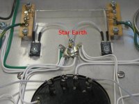
In the example photo above, the green wire also connects to the star point along with the other signal returns, so there is really no current between any 2 circuits passed through this connection. This connection is the ground, hence no potential difference between this point and any relevant "ground".
Sorry for seeming dense, but I'm not following how a star ground can have a voltage offset... to where?
Cheers,
Michael
Star ground can have a voltage offset to a star ground in another box that has common connection through the power outlet.
Almost every new studio recording hobbyist have to solve the main mystery problem, why his records have strange beeps and screeching sounds until realizes that the cause is in EMI filters in computers and other gear that protecting mains from SMPS noises create noise peaks on ground wires. If to put such filters in some gear that don't have SMPS inside such problems are guaranteed. If somebody wants to protect their gear from EMI both wires can go through ferrite core, but green-white ground wire should be connected directly to the chassis. And no Y-capacitors to ground!
Almost every new studio recording hobbyist have to solve the main mystery problem, why his records have strange beeps and screeching sounds until realizes that the cause is in EMI filters in computers and other gear that protecting mains from SMPS noises create noise peaks on ground wires. If to put such filters in some gear that don't have SMPS inside such problems are guaranteed. If somebody wants to protect their gear from EMI both wires can go through ferrite core, but green-white ground wire should be connected directly to the chassis. And no Y-capacitors to ground!
Star ground can have a voltage offset to a star ground in another box that has common connection through the power outlet.
Almost every new studio recording hobbyist have to solve the main mystery problem, why his records have strange beeps and screeching sounds until realizes that the cause is in EMI filters in computers and other gear that protecting mains from SMPS noises create noise peaks on ground wires. If to put such filters in some gear that don't have SMPS inside such problems are guaranteed. If somebody wants to protect their gear from EMI both wires can go through ferrite core, but green-white ground wire should be connected directly to the chassis. And no Y-capacitors to ground!
Sure there are common ground issues, and ground loops if signal cable shields are connected at both ends to star grounds. This can be resolved by having a pin 1 convention grounded at outputs only for example. Then, how does this noise get into the signal path? Are some of the so-called balanced interfaces actually not rejecting common mode noise? Is the power supply design allowing common mode power line noise through?
I've had good luck in measurement setups by using an isolation transformer and single point system ground. That shouldn't be needed if proper balanced interfaces are used.
outboard power supplies?
Given that one has an umbilical cable from an outboard power supply, what's the best way to arrange the grounding?
Do I do most but not all of the filtering in the outboard unit and then set up the star ground on the amp proper with the final filtering cap negative terminal going to it?
I have a 3 leg pi filter (CRCRC) so I figured that having the first CRC in the outboard supply and the final filter local would be best practice anyhow...
Thoughts?
- Status
- This old topic is closed. If you want to reopen this topic, contact a moderator using the "Report Post" button.
- Home
- Amplifiers
- Tubes / Valves
- Ground Plane vs Star earth