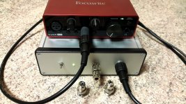
I’ve put some resistors in the BNC connectors to be used as baseline reference while preparing REW for the measurement. Using 1500 Ω (5 nV/Rt Hz), 39 kΩ (25 nV/Rt Hz) and 150 kΩ (50 nV/Rt Hz) measured noise density was in accordance with used resistor. However, I noticed that noise spectrum was falling toward high frequency for bigger resistor values, but low frequency noise density was always spot on.
Using different FFT windows, FFT appearance was changing but noise density always remained the same. So, it looks that REW software has included proper FFT scaling in respect to the noise power bandwidth of used window.
With calibrated REW, min. preamplifier noise density was 460 pV. That is in line with previous syn08 remark that 2SK3557 has 5-10% higher noise than BF862.
Considering all, I declare a successful build.
Attachments
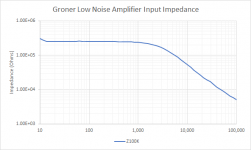
With regard to the input impedance. I ran two tests a couple times. The first with a 100k resistor in series with the input, the other straight input. The current across the resistor is the difference in voltages divided by 1000, divided by the resistor value. The input impedance is then the lower of theses voltages divided by the current. My network analyzer has a hard time with impedances over 10k, so did it the old fashioned way.
If you need higher input impedance lower the gain to 100x:
If you need higher input impedance lower the gain to 100x:
Attachments
I’ve put some resistors in the BNC connectors to be used as baseline reference while preparing REW for the measurement. Using 1500 Ω (5 nV/Rt Hz), 39 kΩ (25 nV/Rt Hz) and 150 kΩ (50 nV/Rt Hz) measured noise density was in accordance with used resistor. However, I noticed that noise spectrum was falling toward high frequency for bigger resistor values, but low frequency noise density was always spot on.
Using different FFT windows, FFT appearance was changing but noise density always remained the same. So, it looks that REW software has included proper FFT scaling in respect to the noise power bandwidth of used window.
With calibrated REW, min. preamplifier noise density was 460 pV. That is in line with previous syn08 remark that 2SK3557 has 5-10% higher noise than BF862.
Considering all, I declare a successful build.
congrats, seems like an impressive test amplifier
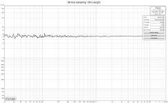
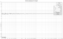
I assume, your FFTs are not scaled for 1Hz right? With 96kHz FS and 256k length, your bins are 2,6Hz wide, so your plot is like 4dB too "high"
can you put the FS and length at the same value? Than your plot will have V / SQRT(1Hz)
I have been writing a small blog about this:
With regard to the input impedance. I ran two tests a couple times. The first with a 100k resistor in series with the input, the other straight input. The current across the resistor is the difference in voltages divided by 1000, divided by the resistor value. The input impedance is then the lower of theses voltages divided by the current. My network analyzer has a hard time with impedances over 10k, so did it the old fashioned way.
If you need higher input impedance lower the gain to 100x:
Thanks for doing this Jack, indeed my problem as I also want to have a >> 1MOhm input for measuring filters. Again of 100 will do as well. Even a gain of 10 would help me as the AP is low noise enough for my objectives
Thanks for doing this Jack, indeed my problem as I also want to have a >> 1MOhm input for measuring filters. Again of 100 will do as well. Even a gain of 10 would help me as the AP is low noise enough for my objectives
I am sure there are other issues, but you can trade off gain by lowering the feedback resistor, R105 to perhaps 300 Ohms. This will get Zin ~740k by my sims. The NE5534 should be able to handle output current of 38mA according to the datasheet.
BUT! There are other issues surrounding the issue of Zin, particularly L101/C103/R103 which are used to offset the negative input capacitance of the amplifier.
What's your noise budget?
can you put the FS and length at the same value? Than your plot will have V / SQRT(1Hz)
Another interesting consideration while taking FFT measurement!
Unfortunately, using REW + Focusrite there is no combination of available sampling rates and FFT length, that has 1 Hz bin width. Taking measurements of the same 5 nV/Rt Hz source with 96 kHz sampling rate and various FFT lengths does not change the result. Seems that REW software takes every option in the math account.
Attachments
You do not need 1 Hz bins to measure noise density. Its a matter of scaling to reflect the bin width and skirts and averaging. However the level of a sinewave won't be properly measured when set for noise measurements.
The lack of an LF corner suggests to me that the noise floor of the Focusrite is set by internal series resistors. Its not really an issue if you are measuring the noise of an amp/preamp since the gain of the DUT should boost its noise above the noise of the Focusrite. Calibration is a bear and resistors are the best way if you don't have a known noise source. What works for me is a resistor box and I increase the resistance until the displayed noise increases 3 dB. Then the noise value of the resistor is the equivalent of the internal noise floor. With an FFT you an see hum and other stuff that would distort the measurement.
The lack of an LF corner suggests to me that the noise floor of the Focusrite is set by internal series resistors. Its not really an issue if you are measuring the noise of an amp/preamp since the gain of the DUT should boost its noise above the noise of the Focusrite. Calibration is a bear and resistors are the best way if you don't have a known noise source. What works for me is a resistor box and I increase the resistance until the displayed noise increases 3 dB. Then the noise value of the resistor is the equivalent of the internal noise floor. With an FFT you an see hum and other stuff that would distort the measurement.
Noise floor is determined by the lab preamplifier in front of Focusrite and is for sure around 460 nV/Rt Hz. Noise corner is present, but is obscured by heavy averaging, which was used to get clear mean values that are easy for comparison.
I will check noise floor with your recommended method.
I will check noise floor with your recommended method.
Noise corner is present, but is obscured by heavy averaging, which was used to get clear mean values that are easy for comparison.
Noise corner frequency is not affected by averaging. Most likely, it's the Focusrite frequency response drop at frequencies under 20Hz, all sound cards I've seen have this limited low frequency response.
The nV did throw me for a loop. .4 nV is a good number for a low noise preamp. Getting lower would need a transformer. The next question is what are you looking at with this? The low noise and high gain are suitable for transducers but may overload on amplifier outputs.
Geoformer? What to recommend.
FWIW, Triad has put all of their catalogs on-line but most pages are low-rez JPEGs
Noise corner frequency is not affected by averaging. Most likely, it's the Focusrite frequency response drop at frequencies under 20Hz, all sound cards I've seen have this limited low frequency response.
You are right on both points, of course, but REW does change result in the LF part of spectrum by using averaging. Using 32 averages, noise corner appears to be 10 Hz or none at all, which is pure fiction. With no averaging, it is visible that noise corner is between 100 to 200 Hz. In the post #279, there are measurements with 16 averages and there is a slightly visible noise corner. With less averaging it is more pronounced. As REW is free software, I have no complaints and just acknowledge how it is.
The next question is what are you looking at with this? The low noise and high gain are suitable for transducers but may overload on amplifier outputs.
I will use this preamplifier for noise and output impedance measurements. Output voltage is up to 30 Vpp, so with 60 dB gain, it can tolerate 10 mV RMS at the input. If needed, I can add 40 dB gain option.
You do not need 1 Hz bins to measure noise density. Its a matter of scaling to reflect the bin width and skirts and averaging. However the level of a sinewave won't be properly measured when set for noise measurements.
The lack of an LF corner suggests to me that the noise floor of the Focusrite is set by internal series resistors. Its not really an issue if you are measuring the noise of an amp/preamp since the gain of the DUT should boost its noise above the noise of the Focusrite. Calibration is a bear and resistors are the best way if you don't have a known noise source. What works for me is a resistor box and I increase the resistance until the displayed noise increases 3 dB. Then the noise value of the resistor is the equivalent of the internal noise floor. With an FFT you an see hum and other stuff that would distort the measurement.
That is really neat -- here's the E(in) of a pair of LT1113 opamps with Rin of 1 and 661 Ohms -- almost exactly 3dB:
Attachments
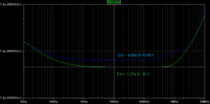
That coincides almost perfectly with the datasheet noise value of 4.5 nV/rtHz. With an FFT you can see LF noise using the same technique. I use this: Thermal Noise Calculator to calculate the resistor noise. Set the frequency range to 1.
However measuring real circuits will show all the other less obvious contributors.
However measuring real circuits will show all the other less obvious contributors.
As dBV scale is relative to 1 V rms, using preamplifier with 60 dB gain, I put in this box 0,001 V.
Second calibration point is to set measured noise level, with shorted LNA input at known noise floor and confirm this with measuring noise of the < 10 K resistor. Higher R values noise is affected by parallel input impedance of the LNA.
That is what I use but there are certainly better methods.
Second calibration point is to set measured noise level, with shorted LNA input at known noise floor and confirm this with measuring noise of the < 10 K resistor. Higher R values noise is affected by parallel input impedance of the LNA.
That is what I use but there are certainly better methods.
- Home
- Design & Build
- Equipment & Tools
- Groner's Low noise measurement amp from Linear Audio vol 3 - spare boards?