I've breadboarded the WE91A 300B circuit from Sound Practices (The Single 300B Amplifier A model 91 for 1992 Article By Joe Roberts Sound Practices Magazine Online), using 6SJ7 for the driver. Voltage and current measurements are all fine except I'm getting about +25mVDC on the 300B grids.
Unless I'm missing something, shouldn't the 300B idle grid voltage be negative?
I've triple-checked my connections and am confident that the schematic is accurately built. I listened briefly and it sounded OK, but I didn't want to let it run too long with that positive grid voltage.
Thanks,
Jeff
Unless I'm missing something, shouldn't the 300B idle grid voltage be negative?
I've triple-checked my connections and am confident that the schematic is accurately built. I listened briefly and it sounded OK, but I didn't want to let it run too long with that positive grid voltage.
Thanks,
Jeff
Voltage and current measurements are all fine except I'm getting about +25mVDC on the 300B grids.
Yes, it's not the grid voltage to ground that matters, but the grid voltage relative to the cathode, Vgk.
The cathode current flowing through the cathode resistor sets Vgk, since the grid resistor goes to ground.
Last edited:
Ah, I see. Thank you. I thought those negative grid numbers in the WE op point tables were referenced to ground.
Now that we're on the subject, what should be the grid voltage for 300B in a grid-biased application?
For instance, for the line that stipulates 350Vak, -74V grid, 60mA into a 3K load, does that mean the grid is +276V referenced to ground, 276V referenced to anode, or -74V referenced to ground?
Now that we're on the subject, what should be the grid voltage for 300B in a grid-biased application?
For instance, for the line that stipulates 350Vak, -74V grid, 60mA into a 3K load, does that mean the grid is +276V referenced to ground, 276V referenced to anode, or -74V referenced to ground?
Attachments
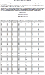
For instance, for the line that stipulates 350Vak, -74V grid, 60mA into a 3K load,
does that mean the grid is +276V referenced to ground, 276V referenced to anode,
or -74V referenced to ground?
This chart implies that the cathode is grounded, so Vgrid is -74V wrt ground (or cathode).
When a voltage is given in the form Vp, that implies it is the plate voltage wrt ground.
If given as Vgk, that is the grid voltage relative to the cathode, not wrt ground.
Last edited:
25mv DC on the 300B grid usually means one of 5 things:
1. The 300B is gassy.
2. The coupling cap from the driver plate to the 300B grid is not a quality low leakage 600V cap. Remove the cap from the driver plate, connect that cap end to ground, and
re-measure the 300B grid voltage. If it is still 25mV, it is likely one of the other causes listed here.
3. The grid resistor to ground is too large of a value. There are 2 specs, one for self bias, and one for fixed bias.
4. One of the 300B specifications is exceeded: filament voltage, plate voltage, plate current, or the plate dissipation (V x I) is exceeded.
5. The 300B is not a quality tube, and/or does not meet specifications.
Paying attention to all of the above, I get about +10mV DC with Russian, Slovakian, and Chinese 300Bs.
Happy troubleshooting, and happy listening.
Thanks, 6A3. That's a very helpful checklist. I would not have known to check those things before.
The tubes are budget Psvane Hi-Fi Series 300B (about $150/pair new), direct from the factory. They are about three years old and probably have about 1,500 hours on them.
Vak = 375V
Vk = 73.4V
Rk = 870ohm
So Ik = 84mA
Assuming Ik roughly equals Ia, the dissipation (375*.084) would be ~31.6 watts. So, close to but not exceeding the maximum 36 watts. Perhaps that's a bit hard to run a budget tube like this?
I tend to prefer the sound when the current on the 300B is closer to the 50-60mA range, so I'm planning to install the 1.5K cathode resistors to try and bring that down. Will be interesting to see if that changes Vg, in addition to the other things in your list.
jdrouin,
I think I may have been a little too conservative. It might be as high as 25mV.
But try the capacitor trick, # 2 above, and read the voltage.
Just remember to keep an eye on the grid voltage from time to time.
The 91 schematic in post #1 has a 390k Ohm 300B grid resistor. But the maximum spec of a self biased 300B, is a 250k Ohm grid resistor.
You might change the 390k to 220k Ohms.
That should keep the tube from thermal runnaway.
The tradeoff is that the input tube gain will go down a little, the maximum drive voltage to the 300B grid will go down a little, and the driver distortion will go up a little.
I once had 2 mesh plate 300B tubes, one of them had over 1VDC on the grid, the tube had really gone South (Bad). The bad one was donated to the garbage man.
I would not *panic* over 25mV on a 300B grid.
The power-on thump of the driver may be hundreds of volts. It decays on an exponential. With deep-bass coupling values, a long exponential. And an exponential "never reaches zero". In quick-check, mV may be normal (but declining).
The bias is 50V-75V; 0.025V one way or the other is insignificant.
"Some" grid current IS normal. How much is often unclear. We usually get involved after it has busted a gut.
Agree that a weak/leaky coupling cap is a BIG concern.
Agree that Rg1(max) ratings should rarely be broken; for costly bottles working hot, a wide margin is wise. (Especially if not sourced from extra-good producers.)
OK, thanks. I've got some 220K carbon comps and will try those.
Was there anything beside the 1VDC grid voltage that told you the tube was going bad?
I just spent about an hour listening to the amp and it has a wonderful bloom. Source was Ella Fitzgerald CD ripped to Apple Lossless format, played via iTunes and my iMac's headphone port to the WE91A. Speakers are DIY Woden Shrike, a folded MLTL with Fostex fe103Sol. Going to move it to my main system tomorrow.
I noticed that I was getting about 10V more B+ today than yesterday, and the filament and heater voltages were a bit high (5.7V on the 300B, 6.6V on the 6SJ7), probably due to line voltage variation. Looks like I'll either need to put some small resistors on those or start using regulator chips.
The Meshplate 300B had self bias, and a grid resistor that was in spec. It was run very conservatively with less than 18W dissipation.
The problem with that tube when the grid that went to 1V, was it kept on going even higher.
Of course the self bias kept going up as a result. I was not willing to wait for it to die during a listening session, or even do some damage.
Going from 120AC line volts to 123 line volts will cause the B+ to go from 350V to
358.75V.
I regularly check my power line volts.
When I build a new amp, I use resistors in the filament circuits to get the filaments to be correct when the power line voltage is at the voltages that I consider to be average over time for my home.
Since I use old transformers that were rated for 115VAC or 117VAC, and my power is 120VAC on average, I always have to use resistors in the filament circuits.
But that means I must pay attention to several details:
1. I always use less draw on the filament windings, and less draw on the B+ windings than the transformer was originally rated for.
2. The filaments warm up more slowly because of the series resistors.
3. The transformer works a little harder due to the primary and core getting 120V instead of 115 or 117V (not enough inductance and core).
4. I use choke input on the B+ whenever possible, the transformer heats up less with choke input.
5. I also use 2 fuses in series, a fast blow that does not blow during inrush current at turn-on, and a slow blow that does not blow during warmed up running current draw. I measure these conditions in order to select the correct values.
Continuing on from my Post # 13:
Resistors in series with the filaments to lower the filament voltage to the design center voltage rating causes a "slow start" of the filament warm-up.
6. That means the B+ will rise to a higher voltage than you might expect, especially if you use solid state B+ diodes; (also for other amplifiers that use indirect heated output tubes). But even your 300B tubes will warm up slowly.
Make sure that the B+ capacitors can stand 1.414 times the secondary rms voltage (the Unloaded rms). And make sure that the peak reverse voltage rating (PRV) of the diodes can also stand 2 X that unloaded rms voltage.
7. Always use a DMM with True RMS AC readings. That goes both for measuring your power line voltage over time to find the range of mains voltage over time, and to measure the filament voltage.
That is because it is not a perfect sine wave going into the transformer, and not a perfect sine wave coming out of the transformer's filament secondary windings.
The filament heats up according to the rms voltage it receives (not the readings from DMMs that measure peak or average voltage to measure AC Volts).
A digital scope that has a true rms measurement feature can also measure the filament voltage.
But for 300Bs, it will not work, since you will not have one end of the 300B filament connected to Ground.
And for power mains measurement, you would have to probe from Ground to Hot, then Ground to Neutral, and then add the 2 voltage readings (with the scope ground clip on mains ground, not on mains Neutral).
Connecting the scope ground clip to Neutral is not a good idea, and I have seen a situation where doing so smoke the ground clip wire (don't try connecting the scope ground clip to neutral at home or at work).
300B filaments are 5V +/- 5%, that is +/- 0.25V; with typical power mains voltage variations that is hard to maintain unless you get it set to 5.0V when the mains is at the middle of the min and max variations.
A good many of the tubes that use 6.3V filaments have +/- 10% ratings, +/- 0.63V.
Last edited:
Thanks again for all that info. I've been at this for more than two years and am still a noob, so any and everything is helpful.
The HT secondary is 400-0-400 (Hammond 378X) rectified by a single 5U4GB into a split rail power supply. OPTs are Tektron 3.5K:10ohm & 16ohm, 100mA.
I put the breadboard into my main system and it sounds good. Of the 300B SE circuits I've tried (Tubelab SE, JE Labs, Fi Primer, George Wright WPA 3.5 modified for 300B, George Wright Mono 8 that I reverse engineered), the WE91A has by far the deepest and fattest bass. Midrange and treble are also excellent, with lots of detail and tonal complexity. It's less "airy" than the Fi Primer when I ran that one at 382Vak/56mA.
There wasn't any smoke, but my nose told me that something wasn't happy. It was running at 370Vak/85mA. When I get home from work I'm going to increase the 300B cathode resistor to lower the current and take off some of that heat.
In the circuits I tried earlier, my preference was for higher voltage/lower current with a 1.5K cathode resistor on the 300B.
My PS caps are 500V, though, so I need to make sure I don't exceed that. Will probably start with a 1K cathode resistor, since I'm currently at 870R.
I'd love to put in my GZ34 to try and get the 300Bs at 400Vak/60mA, but will probably need higher voltage PS caps for that.
I swapped in a 1K cathode resistor. B+ and other voltages are the same, but now the cathode is at 76V which means it’s drawing about 76mA. The amp is running much cooler and doesn’t sound quite as “thick.”
I’m going to try a 1.5K and then swap in the GZ34 to see if I can get about 400Vak/60mA.
I’m going to try a 1.5K and then swap in the GZ34 to see if I can get about 400Vak/60mA.
Quick update on 300B circuit mods: 240K carbon comp on the grid and 1.5K on the cathode. Running at 56mA and ~382Vak -- sounding best to my ears so far. Will add a 220K to the grid to listen for changes.
Lost sound in the right channel last night. Looks like the 6SJ7 has died, since all connections around it check out. The plate voltage on that one was consistently about 30 volts lower than the left channel one, so I assume it had been on its way out (even though it sounded good).
I ordered a matched NOS pair to replace it.
G2 supply voltage was also pretty close to the 125V max, at like 121V. I'm going to bump up R8 from 75K to the neighborhood of 77-80K just to bring it back from the edge of max and (I hope) ensure longer tube life.
This is definitely a circuit I plan to develop. Eventually I'd like to try 6C6 and C3M as input tubes, with 0D3 regulator on the supply grid.
Last edited:
Don't forget that when you are calculating dissipation, you subtract what is dropped in the cathode resistor to determine cathode to anode voltage, so your above example of 382 - 84 (56ma across 1500 ohms) gives 298v a-k, at 56ma gives 16.7 watts dissipation (tube should last a long time!). I built a 91 clone as well, inspired by the same article. I use a vr105 to set the screen on the 6sj7's at 105v, anode is around 210, 300b's are running at about 22 watts dissipation. Sounds great and I use it (or a pp 2a3) to drive GPA 604's.
jdrouin,
The 91 schematic in post #1 has a 390k Ohm 300B grid resistor. But the maximum spec of a self biased 300B, is a 250k Ohm grid resistor.
You might change the 390k to 220k Ohms.
That should keep the tube from thermal runnaway.
The tradeoff is that the input tube gain will go down a little, the maximum drive voltage to the 300B grid will go down a little, and the driver distortion will go up a little.
I didn't have any 220K on hand, so I put in a 240K grid leak resistor just to keep it under 250K max and feel that the 390K sounded slightly better.
Just wondering what the risk of a 390K grid leak is? It seems the WE amps ran that way in movie theaters well into the 1980s.
- Status
- This old topic is closed. If you want to reopen this topic, contact a moderator using the "Report Post" button.
- Home
- Amplifiers
- Tubes / Valves
- Grid Voltage in Sound Practices WE91A