Thanx Graham,
We clearly have a mystery here, a quick look would have me guess that the current sources in your JCX implementation would actually give it the advantage in slightly more loop gain than your bootstrap/resistive bias which should result in reduced output impedance – does your JCX output impedance change when the bias regulator is removed (just change the sense Rs to microOhms and adjust the driver bias)
I will see if I can find the gain difference in LtSpice, can you share your transistor models or are you constrained by your simulator’s copyright? – we could argue that this would be a noncommercial “fair use”
Hi Carlos,
'SMOKIN'
Your soldering iron I mean, not the 12-bore !!!
Hi jcx,
I am personally sure that there is no value to be gained from further examing output device sensed bias control. I first investigated things like this in the '70's, and I had already moved on beyond this recently published 25W-8R class-A circuit before it was submitted.
Can I suggest that you place a milliampmeter in series with your bias control transistor collector, and the driver transistor collector and observe their currents under 'back emf' drive.
Cheers .............. Graham
Hi John,
Had a chance to try device parameters as you suggested, then ended up with your bias circuit performing 6dB better than my plain amplifier.
Started afresh with two copies of my amplifier, and then remodified one to add your current sources with the bias transistor.
Damping characteristics - dB and phase - now virtually identical.
(My simulator is a nightmare because it occasionally forgets entered device parameters and reverts to stock figures after a Save and re-opening; can be a real nuisance having to always re-enter for parallel push-pull with modern drivers plus outputs!)
Your biasing arrangement has five more transistors than my original, without much real world advantage.
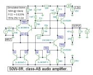
It is possible to double the output of my amplifier for the same quiescent dissipation by adding two small signal transistors as with the attached circuit. I first did this for 100W - 4 ohms in the 1970's using triple parrallel 2N3055. Actually the dissipation can be further increased, but the amplifier is then a little slow to 'warm up'.
Apologies for my curves causing consternation, it is a genuine simulator problem that can catch me out when running quick checks.
Cheers ............ Graham.
Had a chance to try device parameters as you suggested, then ended up with your bias circuit performing 6dB better than my plain amplifier.
Started afresh with two copies of my amplifier, and then remodified one to add your current sources with the bias transistor.
Damping characteristics - dB and phase - now virtually identical.
(My simulator is a nightmare because it occasionally forgets entered device parameters and reverts to stock figures after a Save and re-opening; can be a real nuisance having to always re-enter for parallel push-pull with modern drivers plus outputs!)
Your biasing arrangement has five more transistors than my original, without much real world advantage.
It is possible to double the output of my amplifier for the same quiescent dissipation by adding two small signal transistors as with the attached circuit. I first did this for 100W - 4 ohms in the 1970's using triple parrallel 2N3055. Actually the dissipation can be further increased, but the amplifier is then a little slow to 'warm up'.
Apologies for my curves causing consternation, it is a genuine simulator problem that can catch me out when running quick checks.
Cheers ............ Graham.
Attachments
Had some off set problems Graham, can you please
Send as soon as possible, some explanation about the circuit , the DC voltages and the calculation of RZ and RB.... almost ready to run, the 50W unit, the new one.
Some support text is beeing needed to turn off set zero.
I want to know the DC voltages, send those informs directly my Mail
regards,
Carlos
")
Yes!, come on!, check your mail.
I am crazy to put this one to produce good sound, now 2 o'clock morning and i am here checking my spider shape assembling, wanna hear it!.
Thank you Mikek, this is one thing that turn me alike a kid again!....want to hear that sound, as i like the other one, this one may be "hot" too.
Graham is sleeping......hello Grah!....good morning!...Charlie calling you!!!
will check the board once more....one day in my life i will understand that assemble amplifiers using 2 inches, by 1 1/2 inches squared board is not a good idea.
Now here, it is near the sunrise....and England is more to east....it is day over Graham home....hello Grah!... wake up man!
Normally i do not talk with you Mikek, because the language...no no no, not the english...your advanced electronics...cannot even talk with you!.... difference too big, i do not even understand the things you say, more recently i perceive that you have a "heart" too, and by this way i start to "recognize" you.
I see you as some guy with 5 feet high, with heavy glasses, carrying a lot of books, half crazy, half gênius...cannot even talk to you... i am too much stupid to maintain some conversation, your words, the Control track of CCS the long tailing process creating a under climate delivery or third order speaker excursion inside the electron orbite....hehe...cannot follow you.
Hey GRAH!...CAME ON!!!!
regards,
Carlos

Hi Carlos,
Do please note that this is a much less technically accurate circuit than pure class-A.
In a simple circuit pure class-A is much more competent, but not efficient and not good into loudspeaker impedance dips.
The extra mirror and resistor are added to pull driver current out of the output stage and thus reduce heat for a given power, but the output device currents are no longer matched and they rely upon NFB for output terminal accuracy.
This circuit also relies upon power rails coming from a single bridge, or at least identically from the same transformer winding so that the bias current and sink current approximately track each other.
Forget R.z unless you want very low output offset potential.
Leave out the additional 820 ohm resistor and first set up as a class-A amplifier with R.b between 180 and 390 ohms.
After you are satisfied that the amplifier works well in class-A insert the 820 ohm resistor so that the mirror sinks output bias, then slowly reduce the value of R.b until the quiescent current comes back up to the required value.
Hope this gets you going.
Please Mr Destroyer, can I go and get my breakfast now ?
Cheers ............ Graham.
Yes, you can, and have a cup of tea in my place...not too much suggar please!
Thanks by your valuable assistance.
The amplifier is now running well and sounding good.
I will call boys to group test... they said i am impeached, as i am "sick" by Mr John Linsley Hood..... i will not vote....how deer them do that with the "Eminent President".
They said i am "impeached", as my judgement not fair when involving JLH Designs.
We have to test fake AKSA against the Hugh Dean AKSA first.
As soon as i have some new i will run to you to tell the news about your amplifier group test results.
regards,
Carlos
Fake Aksa is only a joke, together hugh, and following his instructions
I was changing AKSA to produce more bass.... i asked Hugh to forget linearity, as the flat amplifier, in my "Perception" sounded too much brigth, this is a result of the high frequency quality of reproduction and the human ears characteristics related hearing low levels.
In the past people had a switch called "loudness"... i was asking that operating only to bass, as the treble, beeing so good was "erasing perceptually" some bass.
But i could not measure problems....it is flat!
I asked him to help me to un flat the amplifier.... to have more pronouciate increase in bass reproduction...... to perceptually ballance to may personal taste, unballancing real amplitude levels related top and low end.
I denominate this amp, the Fake AKSA, it is not, it is Hugh cooperation with me, to make some adequacy to my ears.
Now , i will compare, if guys free, will be today, not sure.... I was losted inside the process, and hugh thinks the difference will be very small... i will see that.
regards,
Carlos
Graham I don't know enough theory to follow all of your recent EW articles but I own a JLH 10watt (69 version) and am interested in this thread. I appreciate your concern with back EMF and your emphasis on an amp' being able to function correctly into real life loads. Are you making a case for flat impedance curves achieving better sound from power amp's. I recall KEF, a few years ago, having quite complicated "congugate matching networks" (I think they called them) and aiming for a v.flat curve.
Hi Jonathan,
Good question.
I aim for minimum output stage reactance, and having as close to zero as possible an output stage *phase* response at and beyond audio frequencies. This means minimum output impedance, which can be quite different to a spot frquency measured output resistance or damping factor.
A low output resistance is necessary to prevent the output terminal voltage of an amplifier from being amplitude modified by loudspeaker generated back EMF, but unless an amplifier's NFB error control response is very fast its output terminal will effectively become inductive; this could lead to sudden leading voltage generation from mid-range back EMF which will simultaneosly modulate tweeter waveform.
The 1969 JLH has approx 30dB of damping (only), but it has minimal NFB delay inductivity and thus generates little additional and sudden tweeter driving error from back EMF at normal listening levels. (It is an excellent starting point.)
I have not actually made a case for flat impedance curves producing better sound, merely illustrated how lower output stage inductance permits less loudspeaker induced amplifier error at the output/loudspeaker terminal. I have though made a case for more critical input and output driven amplifier testing, including pre-'steady sinewave' first cycle investigations.
Cheers ............. Graham
Hi Graham,
At the end of part 6 of your article in Electronics World you asked "What's inside your amplifier?"
This is what's inside mine (one of a pair as IMHO the correct place for a power amp is next to the speaker).

webpage at: http://www.susan-parker.co.uk/zeus.htm
... which includes a schematic. Please note that the audio path is NOT simplified. It is exactly as shown.
I am experimenting with IRFP140's as they are a lot cheeper and have a lower input capacitance than the IRFP150's.
The amp has minimum output impedance and the MOSFETs a 1MHz bandwidth.
Best wishes,
Susan.
At the end of part 6 of your article in Electronics World you asked "What's inside your amplifier?"
This is what's inside mine (one of a pair as IMHO the correct place for a power amp is next to the speaker).
webpage at: http://www.susan-parker.co.uk/zeus.htm
... which includes a schematic. Please note that the audio path is NOT simplified. It is exactly as shown.
I am experimenting with IRFP140's as they are a lot cheeper and have a lower input capacitance than the IRFP150's.
The amp has minimum output impedance and the MOSFETs a 1MHz bandwidth.
Best wishes,
Susan.
Transformer non-linearities ?
Hello Susan,
Interesting concept. Perhaps you should start a new thread, so that we don't highjack Graham's thread for a different discussion.
But one issue that bothers me slightly -- how do you deal with non-linearities in your tramsformers? Even audio transformers are not perfectly linear, which is why people still use some negative feedback in valve amps ??
And how much ouput power is your current implementation delivering ?
Patrick
Hi Patrick,
You wrote "Perhaps you should start a new thread, so that we don't highjack Graham's thread for a different discussion."
My post was in reply to Graham's question ""What's inside your amplifier?" in his Electronics World article, so I hope he doesn't take offence.
My amplifier does actually run in Class A (as I understand the definition but all these Class variations gets confusing very quickly) as neither MOSFET turns off at any time (during normal operation) - but this isn't the same as my understanding of normal Class A operation.
An inportant thing to understand is that the output transformer's primaries swing negative as well as positive and the bottom MOSFET for that half of the cycle is still powered but "idles" with most of the current flowing through the MOSFET going positive.
This tracking is because I am using the MOSFETs as Gate Followers, not as amplifiers. Thereforethe transformer arms follow the the gate input voltage minus the MOSFET bias level - the actual gain is a little less than unity.
So both MOSFETS are activly working the whole time.
My amplifier is an Impedance Amplifier, based on the use of transformers as the active elements.
Non liniaraties don't seem to be a problem in the overall scheme of things. A number of Valve amps don't use feedback and loudspeaker drive units are definately non-linear.
As seen in the pic I have about 35 Watts into 8 ohms.
I have bench tested bigger transformers up to 120 Watts however the top end frequency response is not so good (i.e. I don't get 300KHz bandwidth).
I advocate splitting low base (where the speaker cone is in piston mode) from the rest of the audio band so I am not undually worried about high powers below 50 Hz as I have a dedicated low bass amplifier for a seperate bass speaker.
Assuming that there is any interest in what I have done than I will have a look and see what to do about starting a new thread - I have only just joined the forum (not been on any others using this format) and my posts are being moderated.
I hope I have not upset anyone by incorrect posting.
Upupa Epops said:What is for sound more " damaging " ? No caps or two transformer in signal path ? What have bigger quality limits ?
Most damaging is negative feedback around the amplifier final output stage driving a reactive loudspeaker load, unless the mechanisms are understood and can be delt with - which is the point of Graham's articles.
I think that phase distortion is a lot more important than straight THD, which is what happens with negative feedback.
I am an empirical designer and just went back to first principles in my design. I don't have the math skills to design the normal solid state amplifiers from scratch so looked for an alternative - and simpler - way of doing the job.
After the work I have done in developing my amplifier I think that Graham has the problem right on the nail.
Should move this to a seperate thread.
BW,
Susan.
Graham Maynard said:Hi Susan,
You've got your EW ! I'm still waiting for mine. Post ?
Will have a look at your amp now.
Cheers ........... Graham.
Hi Graham,
I bought my copy in Borders (Charring Cross Rd.) last night.
Thanks.
Best wishes,
Susan.
- Status
- This old topic is closed. If you want to reopen this topic, contact a moderator using the "Report Post" button.
- Home
- Amplifiers
- Solid State
- Graham's Class A/JLH output