That is the overall voltage gain on the O2 since the second stage is set up as a unity gain (voltage gain = 1) current buffer. Only the first stage provides voltage gain.
That makes perfect sense now that i look at the circuit diagram, so basically the 2068 chip does the amplification, then the two parrallelled 4556's add the oomph. Question though, whats the purpose of the tiny 1ohm resistor on the outputs?
As guidance on how much gain you need, this table here may be helpful. The ODAC basically delivers CD player output level, so you can apply the results as-is. Grados are listed with -7 dB, so unity gain is plenty.
Another interesting read, thanks. I only noticed last night the silk screen on the PCB says 464r not 464k, and sure enough when i dug out the parts bag a 264 ohm resistor was supplied with the kit. I swapped them in for a test and confirmed 1x gain is spot on, 12 o'clock on the volume is around my comfort limit.
Back to your original post, and playing with your website does 464r for Rf, 121k for Rg, and a 10k pot sound like a suitable combination? Using the calculator on your site those figures give me nice low noise and 1x gain. I am just unsure on the relationship of Rg vs other components, and i cant really see any gains from raising or lowering that value. Should it closely match the value of the pot or whats the theory behind it?
You have got it all wrong. See attch. I hope you are not using HD650 for testingUse only elcheapos h/p
The switch supplied with my kit is a two pole, double throw, i.e. 6 pin. I assume the intention was to wire both the + and - rail through the switch. I totally agree, use crappy cans while testing as i have experienced the missing rail popping sound first hand, not pleasant to the ears or the cans. I've also noted on my scope the - rail takes longer to discharge on power down so you get that imbalance and noise when powering off. As i have read its always good practice to disconnect the headphones before powering on or off for that reason. Personally i will NEVER plug my HD650's into this amp, just no.
Hi, Inside the wood chassis of Ra1, what is the paint applying on surface? It must be conductive, but what is it?
I would like to know too as i was thinking about a wood cigar box enclosure, as an alternative i was thinking of lining the box with some of this..
2m Adhesive Copper Foil EMI Shield Tape Conductive 50mm width | eBay
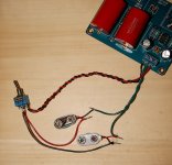
This is how I have it now but I don't think the switch connection is right.
I was guessing you may have wired it up that way, with one (or two) batteries into the PCB +/- terminals and no center ground connection.
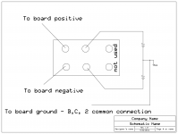
availlyrics' diagram will fix up your circuit. Another is below. You don't use 2 of the 6 terminals on the switch. Their connection diagram on the website is also not clear that the center connection between those two batteries (ground) connects to that common connection of the B, C and "2" parts. There should be a hole on the PCB marked "ground" or with a ground symbol that connects to that point.
Attachments
That makes perfect sense now that i look at the circuit diagram, so basically the 2068 chip does the amplification, then the two parrallelled 4556's add the oomph. Question though, whats the purpose of the tiny 1ohm resistor on the outputs?
That is right about the 2068. To be more exact you can say that the NJM2068 stage does "voltage amplification" while the NJM4556A stage does "current buffering" (sources or sinks more current but provides no voltage gain).
The 1 ohm resistors act to balance up the two sections of the NJM4556A that are being paralleled. Without the 1R's the two sections can "fight" with one section trying to sink/source a lot more current than the other.
Thanks again for your help
I think I have it wired correctly but can't get the switch to work properly. With the 2 wires from the board on one side of the switch it will not turn on. If wired to the other side it will not turn off
Any suggestions?
I think I have it wired correctly but can't get the switch to work properly. With the 2 wires from the board on one side of the switch it will not turn on. If wired to the other side it will not turn off
Any suggestions?
Attachments
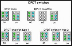
I have been looking at switches and all I can find for the two pole double throw switches are on-on or on-off-on or on-on-on which means that either on side is on at a time or both at once without an off possition. What kind of switch allows you to turn on/off both sides at the same time or is it a different wiring that is required?
Here are some sample layouts that I found. Have to admit it's rather confusing
Here are some sample layouts that I found. Have to admit it's rather confusing
Attachments
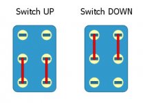
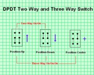
The original switch is a two pole on-on type, power in the center pins, depending on the switch position the output is directed to the top or bottom row of pins, if you only connect one row of pins it functions as an on/off switch.
Its a toggle switch basically, then the on-off-on and on-on-on switches have a middle position where they dont direct power to either sets of pins.
Its a toggle switch basically, then the on-off-on and on-on-on switches have a middle position where they dont direct power to either sets of pins.
Last edited:
Thanks mcandmar- Doesn't this amp require a switch that turns on both top and bottom row of pins to turn on both batteries at the same time and then turn them both of at the same time?
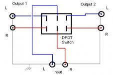
The (DPDT on/on) switch on the top left of this image is what you want, imagine the middle two pins are connected to the battery + and -, then the top row are connected to the + and - inputs on the board. Each column Green and Cyan are separate poles so its basically two switches in one, when you flick the switch both the + and - are being switched at the same time.

From your photos , I think you have opamp soldered directly on board i.e. no DIP8 IC sockets are used. If that is the case you will have difficult time de-soldering the IC without damaging your PCB. I hope you have de-soldering pump or wire braid.Also if you really did accidentally reversed the supply- your electrolytic caps may also need replacement. I wont ask you to remove opamps from your O2 for testing unless your wirings/switch are perfect.Otherwise you may have another dead amp.
I have used NE5532, TL072/82,JRC4558/80 (jelly beans, good enough only with a series 120R at o/p), OPA2134 (CMOY fan's favourite with very low offset). Try these if locally available.Though none of the above opamps can match the performance of JRC4556 (direct o/p into 16R).
Re-check everything thoroughly before proceeding with repairs/ new orders.
BTW does Digikey charges 40$ for S&H?
Hi availlyrics- Thanks for your reply.
I have the opamp mounted on a socket. The original one shipped with the kit seems totally dead- no sound at all. I swapped it out for an OPA2134 from a not working CMOY. It is with that opamp that I have the problems described in my earlier post. It may be that the 2134 is faulty as well. Only a new opamp will tell. I will get a couple different ones when I next order from DigiKey. BTW they only charge $8 for overnight shipping here.
cheers- prezden
Some potheads might disagree there...Vol.control on mp3 player or PC is far more accurate in tracking as compared to the best/expensive pot. In short no need for pot.
All kidding aside, the volume pot provides a variable attenuator, which tends to prove handy when source noise is too high for the headphones/earphones in use even with a unity gain follower, let alone more gain. In fancy terms, it provides a means of dynamic range management. Dynamic range can be shifted downwards as needed. Without this ability, source SNR requirements may become very strict.
If you insist on not using a pot, remove it and connect former pot signal input to former pot wiper.
- Home
- Amplifiers
- Headphone Systems
- grado ra1 clone