This is all getting a bit muddled. ")
What the 3 ohm and second 10uF DO is lifts the very top end (around 10kHz) by about 4dB. I'd guess this is a T27 thing, where it is falling away. I'm guessing you don't need this. So you omit this section and apply your attenuator. The 0.6uF adjusts the crossover slope and attenuates output slightly. It may do no harm to fit it.
You can be quite clever and use the 3 ohm position as the first leg of your attenuator. You can try 3 ohms and maybe 15 ohms shunt across the SEAS tweeter. It may be that 4 ohms is about right, leading to this:
Attachments
I was just running this past BoxSim. The 0.6uF actually LIFTS the output a couple of dB at crossover. It does something to flatten the tweeter response too, so seems a GOOD THING.
To adjust tweeter level with your 12 ohm shunt fitted, you adjust the 2 ohm series UP to 3 ohm or 4 ohm. This reduces the overall tweeter level in a fairly sensible way.
To adjust tweeter level with your 12 ohm shunt fitted, you adjust the 2 ohm series UP to 3 ohm or 4 ohm. This reduces the overall tweeter level in a fairly sensible way.
I'm getting about 3kHz crossover, as it goes.
What it boils down to, is lose the second 10uF, because it isn't helping at all. 12 ohm shunt on the tweeter and adjust between 2 and 4 ohm series for tweeter level. This treble brightness is for your ears alone to decide, because we're guessing on tweeter levels.
Fitting the 0.6uF is really not a big deal, but I quite like what it does, and so do KEF and Falcon, so I'd use it. It gives you a bit more presence around 3kHz. Which is metallic guitar harmonics FWIW.
Last edited:
This is probably a good point to have a review of what has been done and what has been achieved. And very good too, IMO.
You've got an officially approved decent response from the bass via Falcon.
All that remains is to match it up to the SEAS ferro tweeter which is more advanced (and flatter impedance) than the 7 ohm KEF T27 the crossover was designed for.
You could go second order with 3.3uF and 0.3mH. You can do the full third order 3.3/10uF thing too. The attenuator is one of your variables. You could also try a Zobel which is probably 6.8R + 0.82uF across the tweet. Play with Phase too. Really your ears and familiar music are your best guide now. Listen out for precise stereo image too.
FWIW, your Boxsim plot looks out of phase at crossover to me. It's certainly set up for standmounting rather than close to a wall. Acoustic power response is more a function of dispersion and maybe best ignored. When phase is right, you won't hear much difference as you stoop to listen or stand up. But all crossovers lobe a bit.
The tweeter is out of phase with the B200 which is what causes the big dip in the plot at 3KHz.FWIW, your Boxsim plot looks out of phase at crossover to me. It's certainly set up for standmounting rather than close to a wall. Acoustic power response is more a function of dispersion and maybe best ignored. When phase is right, you won't hear much difference as you stoop to listen or stand up. But all crossovers lobe a bit.
This is what the plot looks like if the tweeter is wired in phase.
Just an out of interest point, How would a Tannoy DTM-8 compare to my chorale? (8" monitor gold i believe)
Attachments
Last edited:
Tannoy Dual-Concentrics are beautiful loudspeakers....Just an out of interest point, How would a Tannoy DTM-8 compare to my chorale? (8" monitor gold i believe)
An 8" ought to be good. I used to use the huge 15" Tannoys in a big reflex box for Disco. They sound like paper speakers, which is what the woofer is. Dispersion isn't very wide and the very top end is probably missing in action, but they create a lovely lively soundstage.
It's only the cost that has ever held Tannoy back from taking about 90% of the market, IMO. A classic design.
I might have the opportunity to pick up some monitor golds for nothing. (DTM-8, 10", 12" or 15" though these bigger ones might be too big for my room) I'll see how it goes.
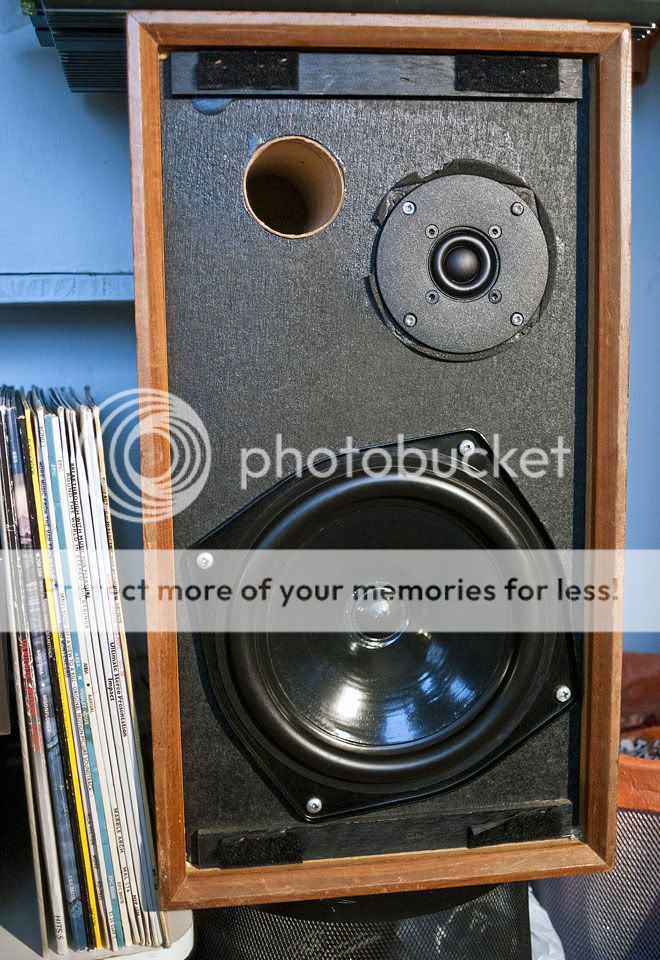
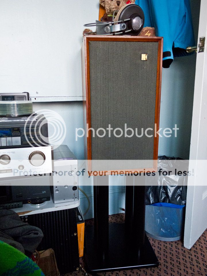
Gave the old cabinets a damn good clean/polish and some beeswax today. All i need to do now is get some new cloth, some KEF badges for the grilles and some proper stands and they'll be perfect.
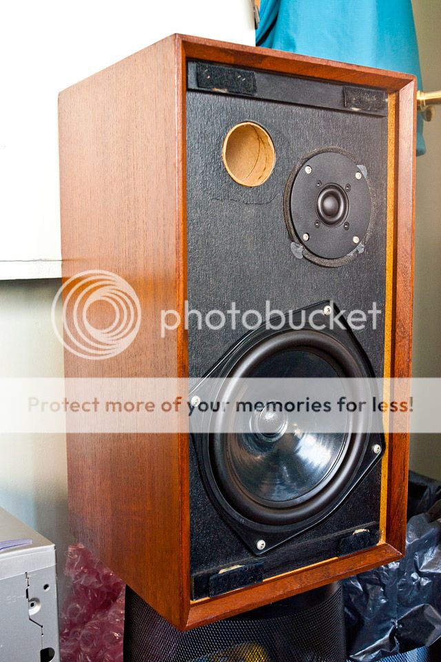
Gave the old cabinets a damn good clean/polish and some beeswax today. All i need to do now is get some new cloth, some KEF badges for the grilles and some proper stands and they'll be perfect.
Having had some more time to play with boxsim, I am confused as to why falcon & Kef choose to wire the tweeter out of phase as it seems to create a big dip in the response at 3k. If i built the crossover exactly to design the response at 3k is down by around 10dB.
You'd use your ears to decide in practise. Turning the speakers upside down and wiring IN PHASE should give you something reasonable at equal distance from both drivers which is above the listening axis. The sim I did with a W200S makes it OUT OF PHASE with 5cm difference in acoustic centres at 3.5kHz. Wavelength being 10cm. 3rd order filters are good at aligning phase on a flat baffle.
You should be adept at listening above and below axis to hear the difference with a familiar piece of music. 3.5kHz is electric guitar high note harmonics. The metallic sounding stuff.

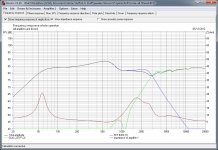
Been having another look at the simulations from boxplot on these. Corrected the big dips in the response with the tweeter out of phase. (due to driver placement on the baffle not being set correctly)
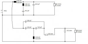
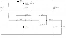
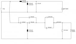
This is the current crossover setup:
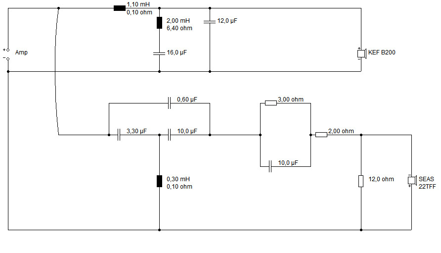
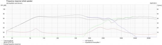
and it's simulation, with a large "hump" in the mid range:
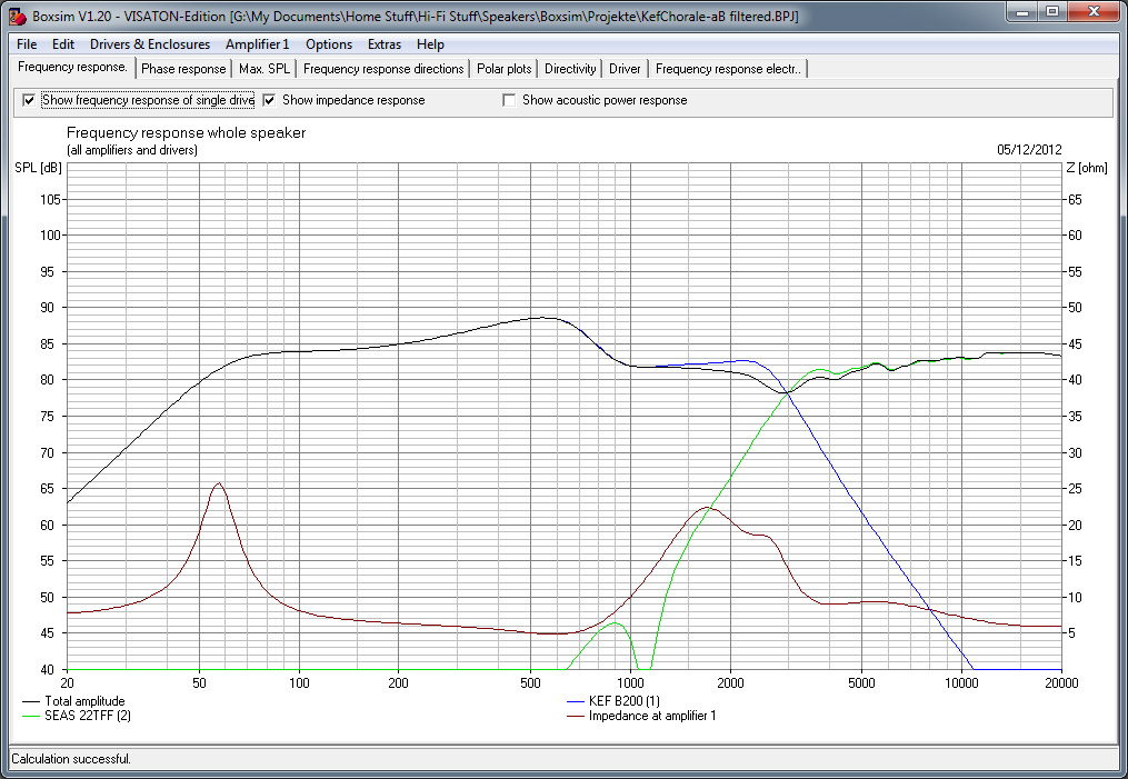
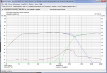
Taking the 16uF capacitor out of the notch filter results in a much flatter plot (taking the whole notch filter out isn't as flat):


I'll have to admit that i cannot hear this large hump in the mid-range, but i still find that they can sound quite bright even with the attenuation. I have noticed that the bass response is much improved when it is simulated as a closed box vs ported. Is there any easy way to close the port easily? Presently is is fully stuffed with dense foam matting, but that doesn't seal them. (and according to boxplot sims, a stuffed port has even worse LF than both open ported and closed box)
This is the current crossover setup:
and it's simulation, with a large "hump" in the mid range:
Taking the 16uF capacitor out of the notch filter results in a much flatter plot (taking the whole notch filter out isn't as flat):
I'll have to admit that i cannot hear this large hump in the mid-range, but i still find that they can sound quite bright even with the attenuation. I have noticed that the bass response is much improved when it is simulated as a closed box vs ported. Is there any easy way to close the port easily? Presently is is fully stuffed with dense foam matting, but that doesn't seal them. (and according to boxplot sims, a stuffed port has even worse LF than both open ported and closed box)
Attachments
This has been a fascinating series of posts. I started out on it as Goodmans Ministers were my first ( proper ) speakers. My memory of them is good, when used with a Sony 1010 amp. ( an expensive piece of kit at the time ) and a Connoisseur BD 1 with a GL75 arm and Goldring 850 cartridge.
Building up and altering these Ministers into Kef type loudspeakers has been an interesting path to follow. In my experience, sometimes a speaker which isn't that accurate can still give pleasing results.
Building up and altering these Ministers into Kef type loudspeakers has been an interesting path to follow. In my experience, sometimes a speaker which isn't that accurate can still give pleasing results.
I think I may have posted the updates on this project in another thread. I ended up buying a calibration mic and using holm and arta got some measurements taken.
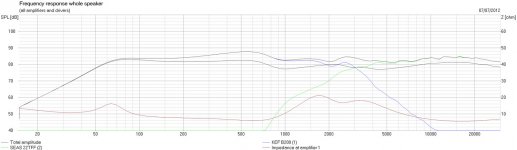
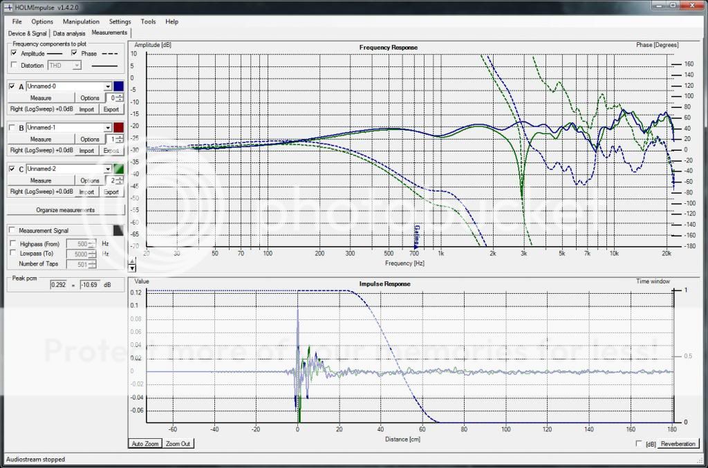
First obvious flaw was the tweeters being in anti phase. Green being anti phase, blue being in phase.
I also noticed a dip in the response at approximately 1KHz caused by the chorale notch filter. This was corrected by damping the filter with a 10R resistor.
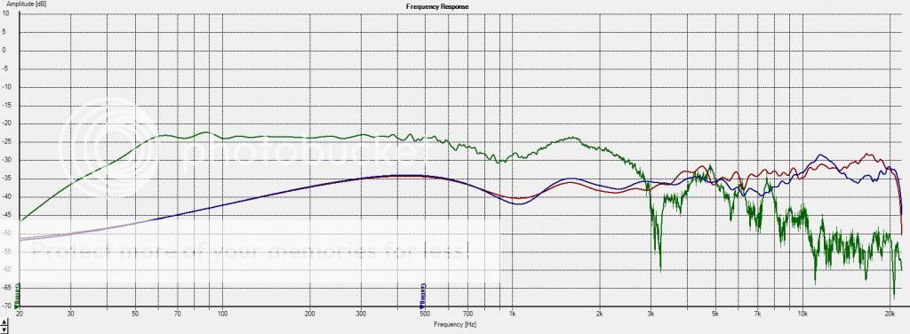
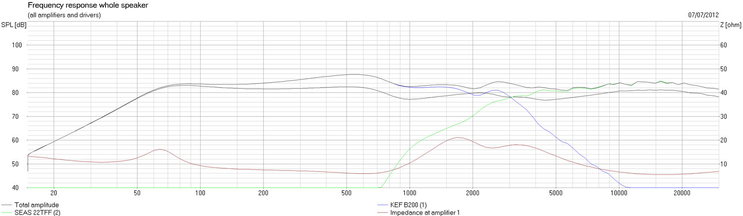
This is the end result after all of the tweaks I made based on the measurements taken. The arta plots are an average of 10 repeated measurements.
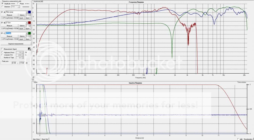
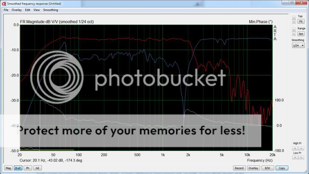
These measurements are far from perfect as i'd need a proper calibrated microphone and an anechoic chamber which i don't have. I'm very pleased considering they weren't built to closely match the chorale spec. The cabinets are larger, aperiodically damped a different shape and the tweeters are totally different. I also sorted out the new grille cloth too. I know that there are better speakers out there but I have to admit that I have really come around to loving the sound they produce.
First obvious flaw was the tweeters being in anti phase. Green being anti phase, blue being in phase.
I also noticed a dip in the response at approximately 1KHz caused by the chorale notch filter. This was corrected by damping the filter with a 10R resistor.
This is the end result after all of the tweaks I made based on the measurements taken. The arta plots are an average of 10 repeated measurements.
These measurements are far from perfect as i'd need a proper calibrated microphone and an anechoic chamber which i don't have. I'm very pleased considering they weren't built to closely match the chorale spec. The cabinets are larger, aperiodically damped a different shape and the tweeters are totally different. I also sorted out the new grille cloth too. I know that there are better speakers out there but I have to admit that I have really come around to loving the sound they produce.
An externally hosted image should be here but it was not working when we last tested it.
Fantastic work, Kei.
You got lucky that the SEAS 22TFF has a Fs of 1100Hz just like the KEF T27 tweeter. So the Acoustic Butterworth notch should have worked exactly right.
That bass filter was tricky, eh? That was the bit that needed fiddling with because bextrene was funny stuff. I've been using this filter a lot myself lately. The treble part is a bit of a classic topology IMO. The notch can be moved around by varying the 0.6uF cap. The bass filter you adapt and change for the drive unit you are using. I've been using 8" paper units and wiring the tweeter with negative polarity.
Hi ! Do you still have all the details regarding the Falcon 37K crossover ? It's not available anymore. I've acquired a pair of Chorales and instead of simply replacing the ALcaps, I thought I'd work on a complete overhaul. I've seen the schematics you posted but I'm lacking inductance values etc. Thnx !I've now got the instruction sheet for the falcon 37K crossover. It doesn't look like it completely follows the original kef design, but i reckon that is to do with their "advanced butterworth filter" for the HF. If the kit comes with bipolar electrolytics, should i stick with them or would it be beneficial to swap them out for MKP? Also it states that the tweeter should be phase inverted as the chorales were, AFAIK my speakers have been running in phase and have sounded fine, should i invert them or leave them? (or is it a case of pick whichever i prefer?)
I've attached the word document that falcon supplied to me. It doesn't list the inductance values. I have the inductance values but I'm not sure on the resistances. The large iron core (L1) is 1.1mH and the large air core (L3) is 0.25mH. The small iron core (Sits in C4 position) is 2mH. This one has a resistance of 6.4ohms according to the info I have on file.Hi ! Do you still have all the details regarding the Falcon 37K crossover ? It's not available anymore. I've acquired a pair of Chorales and instead of simply replacing the ALcaps, I thought I'd work on a complete overhaul. I've seen the schematics you posted but I'm lacking inductance values etc. Thnx !
Attachments
- Home
- Loudspeakers
- Multi-Way
- Goodmans Minister