Logically then i should apply the HF attenuation at the tweeter itself, so 12R across the terminals and 2R in series with the + terminal.
As for moving the speakers around to suit the cardas guide, there simply isn't sufficient space to move them as the room is no more than 3.5m square. (not got a tape measure to hand to check)
As for moving the speakers around to suit the cardas guide, there simply isn't sufficient space to move them as the room is no more than 3.5m square. (not got a tape measure to hand to check)
System 7, Prehaps you could explain to me a bit further how a notch filter would work.
Here is my interpretation bassed on what I know..
A null is opposite to a peek
To attuate a peek, you can work on that specific range with an L-pad, to bring that frequency range leval with the rest of the drivers responce
To attuate a null, it stands to reason that you would be atuatting everyother frequency to be leval to the null, I deduce this because you canot amplify a specific area of responce with a passive network. You can only use resistance. In my mind that is a huge overall sensitivaty loss. Especially if your talking 6-12db!
Do I have a correct understanding? Thanks
Yup. It's always a GOOD THING to shunt a resistor, or failing that a Zobel across a tweeter. Makes for a bit of self-damping and helps control the Fs resonance too. Transistor amps get a bit harsh with high impedance at the top end too, so it's win-win.Logically then i should apply the HF attenuation at the tweeter itself, so 12R across the terminals and 2R in series with the + terminal.
snip
Onto WaveInform's notch/trap question. Traps are better IMO, because they avoid low impedance. Obviously any filter which uses resistors is going to lose some efficiency, but traps are brilliant. I use this calculator to work out series or parallel LCR filters for Q and frequency:
Alan Yates' Laboratory - VK2ZAY's Engineering Calculators - LCR Resonance
Once you have a working circuit, you can adjust Q with resistor value, or changing L and C as long as you keep the product constant. It gets easier with practise.
")
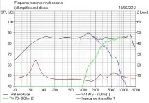
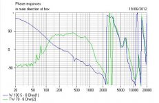
Here's how I fixed the awful 1300 Hz resonance of the Visaton W130S 5" woofer. The deep notch is created by taking out the resistor. This lets you see exactly where it operates. Another technique is to notch a particularly nasty resonance with a TANK, which is a capacitor and resistor across the bafflestep coil, but it does nasty things to impedance at high frequency and is a last resort.
One of the nicest speakers I have ever simmed. A tiny little 12L design with everything right about it. You should visit Visaton and download BoxSim. The Visaton Casablanca III model would interest anyone trying to build a 3 way.
Attachments
I've now got the instruction sheet for the falcon 37K crossover. It doesn't look like it completely follows the original kef design, but i reckon that is to do with their "advanced butterworth filter" for the HF. If the kit comes with bipolar electrolytics, should i stick with them or would it be beneficial to swap them out for MKP? Also it states that the tweeter should be phase inverted as the chorales were, AFAIK my speakers have been running in phase and have sounded fine, should i invert them or leave them? (or is it a case of pick whichever i prefer?)
Attachments
I don't think the phrase KEF used for ab is "Advanced Butterworth", more "Acoustic Butterworth".
IIRC, third order tweeter with second order bass works best with the tweeter wired out of phase.
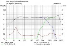
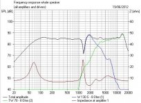
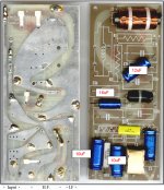
On a flat, non-time aligned baffle it is surprisingly and impressively phase aligned. I'd expect the Falcon offering to resemble the tweeter section of the KEF 104ab below. The upper section, Zobel or notch, is second order.
For all that, some work remains to be done getting a SEAS ferrofluid tweeter to resemble the KEF T27 exactly. But doable, I feel.
IIRC, third order tweeter with second order bass works best with the tweeter wired out of phase.
On a flat, non-time aligned baffle it is surprisingly and impressively phase aligned. I'd expect the Falcon offering to resemble the tweeter section of the KEF 104ab below. The upper section, Zobel or notch, is second order.
For all that, some work remains to be done getting a SEAS ferrofluid tweeter to resemble the KEF T27 exactly. But doable, I feel.
Attachments
Last edited:
I shall certainly find out. I've done a simulated EQ of how the new crossover should work. (5-6dB cut at 900Hz and 4dB cut from 3.5KHz) and it sounds far better, though the notch at 900Hz was weird at first. Presumably I'd be OK to swap any bipolar electrolytic caps out for film?
Be interested to see your sim, Kei.
On reflection, the phase issue is actually to do with how deep the bass unit is. On shallow small ones like the W130S or B110 you probably wire 2nd. Order Bass and 3rd. Order Tweet in phase. With deeper stuff like a B200 it works out as out of phase. This is because the wavelength is quite short at 3.5 kHz.
I'd give the Falcon crossover a go before stripping non polars out. I believe Falcon have fitted a 0.6uF film type in one position, presumably the most crucial. TBH, you have to listen VERY CAREFULLY to hear the difference.
It wasn't a visual simulation (poor wording there), just used an 18 band equaliser to approximately reproduce the notch filter and the tweeter attenuation. The tweeter attenuation certainly helped as it sounded akin to the dittons i just fixed. (They helped me to realise just how bright my speakers were) I haven't got any tools for measuring so i'm unlikely to ever find out, though i did have someone offer to perform the necessary measurements and make some custom crossovers. I didn't go for this as it meant shipping the speakers off for however long and probably costing the earth.
I've already got some 3.3uF MKP caps laying around so i may just swap them over for now and then gradually swap the rest in due course. I found that the difference between film and a new electrolytic is extremely small anyway.
I've already got some 3.3uF MKP caps laying around so i may just swap them over for now and then gradually swap the rest in due course. I found that the difference between film and a new electrolytic is extremely small anyway.
I'd guess that replacing the non polar 3.3uF in the tweeter crossover with a film type is a no brainer. Do it. It's the most stressed component in the high pass.
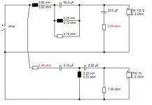
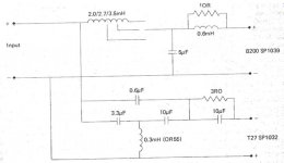
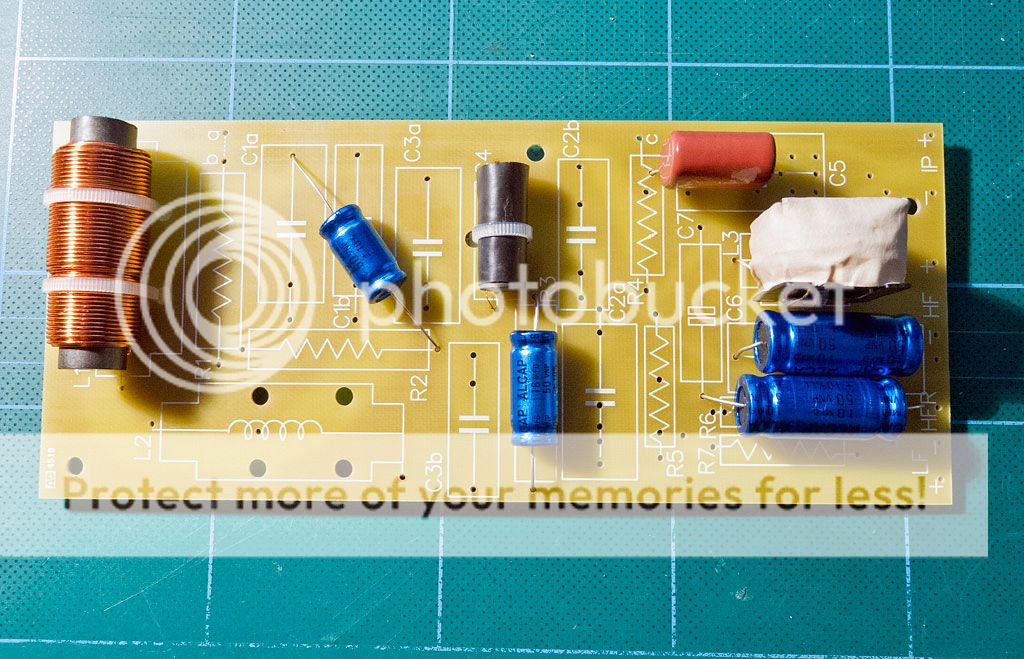
Here's the way the Falcon crossover is going to look with your SEAS attenuator:
I'd guess you will lose the 0.6uF and the 3 ohm/10uF sections. That's a bit KEF T27 specific.
Oh wait, Falcon have slipped a 12uF in there. Not a big deal, but wait and see, eh?
Here's the way the Falcon crossover is going to look with your SEAS attenuator:
An externally hosted image should be here but it was not working when we last tested it.
I'd guess you will lose the 0.6uF and the 3 ohm/10uF sections. That's a bit KEF T27 specific.
Oh wait, Falcon have slipped a 12uF in there. Not a big deal, but wait and see, eh?
Last edited:
Do you reckon i should fit it with the 0.6uF and the 3 ohm/10uF sections to start with and take them out if they are unsuitable or just leave them out from the start?
They are both TINY corrections at the very top end really. Hardly audible, I'd think. My inclination would be to lose them and go for the simplest filter. You should be on solid ground with the attenuator which will sound good IMO.
Fitted the crossover that i built yesterday and compared the two. (initially i wired it up wrong with the Tweeter connected to HF - instead of HFR meaning it only went through one of the 10uF caps) Now it's correct, I cannot believe that i managed to live with it the way it was before as the old crossovers give an extremely sharp sound. Not too sure on the notch filter, might just take some getting used to as I've lived with these speakers as they were for a long time. (resistance measured correctly so I believe they will be filtering as they should)
I'm not quite following what you are doing here, Kei.
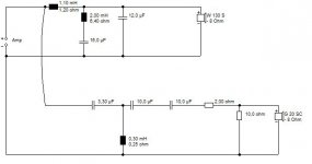
Are you currently at the highpass layout in the first diagram? Two 10uF in series makes a 5uF, which isn't where you want to be with a butterworth IMO.
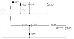
It's not far different from the original KEF Chorale design which is a bit sub-optimal, as shown in the second diagram. You generally only use identical capacitor values when the input filter is attenuated with 6 ohms resistance or so. Otherwise it's a 1:3 capacitor ratio (3.3uF and 10uF) for a filter with no input resistor. This avoids a peaky filter.
Are you currently at the highpass layout in the first diagram? Two 10uF in series makes a 5uF, which isn't where you want to be with a butterworth IMO.
It's not far different from the original KEF Chorale design which is a bit sub-optimal, as shown in the second diagram. You generally only use identical capacitor values when the input filter is attenuated with 6 ohms resistance or so. Otherwise it's a 1:3 capacitor ratio (3.3uF and 10uF) for a filter with no input resistor. This avoids a peaky filter.
Attachments
Yup, and that's not good!I've built the crossovers to match your first diagram. (2x 10uF in series with the 3.3uF followed by the L pad)
The original KEF Chorale tweeter filter with two 5uF capacitors and 0.2mH was excellent for a valve amp with an output impedance of 6 ohms, but for solid state 3.3uF and 10uF and 0.3mH is better.
The exact details depend on modelling, but for sure, the second 10uF is not helping your cause unless you add a 3 ohm in parallel.
- Home
- Loudspeakers
- Multi-Way
- Goodmans Minister