This might help:I prefer not no use TO-3 types.... Which ones would be the better choices?
Output:
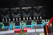
10N20/10P20 from Exicon is far more better than 2SK1058/J162, more punchy bass.
8 Amp 2SK vs. 8 Amp Exicons. I don't have double die Exicons.
2SK and Exicons are similar (or not that noticeably different) at mid-high, but substantial difference at bass!
It's punchy, vivid bass.
I never go back to 2SK/2SJ after that trial, always Exicons, though much more expensive.
BTW, I use plastic TO-247 10N20/10P20.
Best,
Eric
Last edited:
Surely, any helpful information would be considered.
But, it's written in French, which is a bit hard for me to digest.
")
Maybe you can post some English translation here so that we can share?
HiSurely, any helpful information would be considered.
But, it's written in French, which is a bit hard for me to digest.
Maybe you can post some English translation here so that we can share?
I have used google translate and here is the result for the first post:
(Only replaced initial hypex SMPS with linear supply since a lot better sound results....)
-----------------
My version has the following differences:
Power supply : 2x 500va and mundorf power caps
Adding regulated power supply to the front end
Add soft start circuit
Addition of DC / overload protection circuit with relay for HPs
Amplification circuit:
-use of eBay clone pcb
-Input with jfet pair 2Sk170 (With low Idss): higher transconductance
-Input polarized to about 75% of Idss (closer to triode characteristic)
Consequently. At the entrance, changes all the other resistances of the circuit
-2 pairs of dual Die lateral mosfet transistors instead of 4 single Die pairs. Allows to install the circuit flat on the heatsinks. Drivers of these transistors connected in parallel (consequence).
-Frequency compensation adapted to component / polarization changes
-Adding RL filter to the output to supply high capacitive load (crossover, cables)
-2 Feedback capacitors Nichicon Muse bipolar (green) in parallel and also with a wima 2uf. It may not be the best one would have to compare with others.
-Use of Led (bright orange) for the main current source of the circuit.
-Bc5xxc transistors with very high HFE
I will try to find the "clown" schématics....
Fab
Last edited:
Hi all,
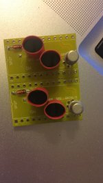
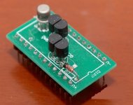
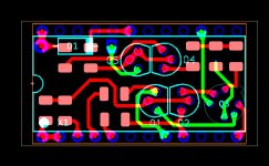
Some progress here. A friend who owns a genuine Goldmund sent me something about module pin definition. I redraw the PCB, very similar to the original one.
2N5564+MPSA42*4+SMD parts, DIP-24
Eric
Some progress here. A friend who owns a genuine Goldmund sent me something about module pin definition. I redraw the PCB, very similar to the original one.
2N5564+MPSA42*4+SMD parts, DIP-24
Eric
Attachments

schematics
Bottom middle - is this the PSU, soft start, DC protect/sense boards?
I am guessing that the schematic is a dual voltage power supply?
Does the soft start have a 12v trigger for on/off?
Who is a good source for these boards and is there a brew your own template available?
I have a few of the 2N5564 parts. Purchased from NJSEMI who god knows where they get them from and the quality. I purchased some mpsa92s when I was there just to get them and the numbers after testing was all over the place. they bragged about selling Boss the jfets for the stomp boxes and well stomp boxes aren't exactly the same as an IPS. I believe LSK389 may actually be a replacement.
YESBottom middle - is this the PSU, soft start, DC protect/sense boards?
I am guessing that the schematic is a dual voltage power supply?
Does the soft start have a 12v trigger for on/off?
YES, another MAINS-12/24V on-board transformer is needed,
Who is a good source for these boards and is there a brew your own template available?
I am not sure if I am allowed to post the commercial source publicly here.
Personally, I do not have plan on doing this by myself. It's for Telos600-5000, complicated and massive-sized PSU.
Though, I am planning to make a PSU-AMP combined PCB, rectifier-filters-amplifier-protection on one single board, with exchangeable input stage modules/sockets.
schematics
maybe i am slow...I can't download these attachments for some reason. I click on them and they expand. Any guidance?
erikovsky
On your Google Wiki you write:
I've tried both Telos and Mimesis.
No, Goldmund Mimesis's sounding is better.
Goldmund Telos have sound more detail, this's will become ''dirty'' with bad recordings.
The Mimesis have more sweet, smooth. Sound is the game of the balance.
Problem is the quiescent current of LTP.
Telos is 4.6mA, Mimesis 2mA.
-currents mirror of VAS must be balanced of currents. This will get the best result. Matching devices is important. Hfe is good enough.
- Try run VAS's currents as low, no more 6mA per side. High current will get the sounding tighter.
Goldmund Telos run at 3.8mA per side. If you can, you need improve the VAS diff pair, to removing Early effect, more linear by a cascode. I've chosen Hawksford cascode.
Telos sound better Mimesis, more detail.
-LTP's CCS of Telos creates approximately 4.6mA for tail current, this current will be shared by two LTP sides. Load of LTP is 1k5.
VAS use FZT857 and FZT957, they are complementary SOT223. It run quite low current than Mimesis, only 7.7mA per both side.
So which one is better Mimesis or Telos?
Or do you say you should use the LTP current from the mimesis and the VAS solution from the Telos to get the best result?
erikovsky
On your Google Wiki you write:
I've tried both Telos and Mimesis.
No, Goldmund Mimesis's sounding is better.
Goldmund Telos have sound more detail, this's will become ''dirty'' with bad recordings.
The Mimesis have more sweet, smooth. Sound is the game of the balance.
Problem is the quiescent current of LTP.
Telos is 4.6mA, Mimesis 2mA.
-currents mirror of VAS must be balanced of currents. This will get the best result. Matching devices is important. Hfe is good enough.
- Try run VAS's currents as low, no more 6mA per side. High current will get the sounding tighter.
Goldmund Telos run at 3.8mA per side. If you can, you need improve the VAS diff pair, to removing Early effect, more linear by a cascode. I've chosen Hawksford cascode.
Telos sound better Mimesis, more detail.
-LTP's CCS of Telos creates approximately 4.6mA for tail current, this current will be shared by two LTP sides. Load of LTP is 1k5.
VAS use FZT857 and FZT957, they are complementary SOT223. It run quite low current than Mimesis, only 7.7mA per both side.
So which one is better Mimesis or Telos?
Or do you say you should use the LTP current from the mimesis and the VAS solution from the Telos to get the best result?
Hi,
These comments are written by member "Walkalone" from Viet Nam, I jsut put them into the WIKI. I think he's saying that Telos is better than Mimesis, due to more detailed sounding.
And yes, he's suggesting Mimesis-LTP+Telos-VAS as a better solution, in my opinion. (so, experiments have to be performed, there're many combinations.)
Telos sounding better,
Mimesis used only 2mA for LTP, its quite low value for JFET input.

Hi,
Some progress here. Thanks to Mr. Kern for kind help.
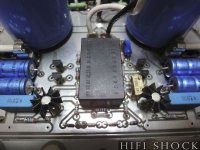
The A2 module has been submitted to manufacturer, it's a phase-1 plan. I will make a amp board with sockets. The module is fully compatible with genuine Goldmund, as Mr. Kern owns a genuine one, then share the pin definition with me.
Also, get some more teardown photos, check out the updated WIKI.
https://sites.google.com/view/goldmund/home
Some progress here. Thanks to Mr. Kern for kind help.
The A2 module has been submitted to manufacturer, it's a phase-1 plan. I will make a amp board with sockets. The module is fully compatible with genuine Goldmund, as Mr. Kern owns a genuine one, then share the pin definition with me.
Also, get some more teardown photos, check out the updated WIKI.
https://sites.google.com/view/goldmund/home
Attachments
When will the boards be ready? Instead of the speced JFET, can lsk489 be used? Actually lsk389 is probably closer to the original specs but has a little more capacitance that needs to be played with and also cant handle the same amount of voltage as the 489.
I remember 489/389/5564 are pin-to-pin compatible.
The boards are arriving.
If you're making a clone then that's a reason to have all those pins and sockets and a separate module.
But if the aim is to make the best possible sound quality then the shortest copper track and least brass (pins) and least possible solder joints, etc, in the signal path makes an audible improvement.
I've done it many times over the last two decades, reducing the signal path for sonic improvement.
Just missing out 10mm of thin track and two solder joints has been audible. Simply taking a feedback resistor off a circuit board, where is may be near to an op-amp, and soldering it direct to the op-amp pins under the board usually gives an audible improvement. Assuming the system and environment (free from extraneous noise) is sufficiently revealing.
Last edited:
- Home
- Amplifiers
- Solid State
- Goldmund Wiki and build 2017