Nelson Pass had some specific criteria on how to derate amps to be reliable, as any single failed amp is an enormous cost for the company. I wish I could find that info
That’s why he has 20 pairs of IRFP’s on a 200w amp.
I hear you. Maybe I can go with two pairs of the Exicons. Conventional heatsink cooling is convenient and quiet. It is so wasteful of mass and volume though.
Holy smokes! I just found this thread, having travelled a completely different path to arrive at nearly the same place! I started out scaling up Jam's HPA-1, but he said it wasn't an ideal topology for higher-voltage rails and pointed me to the Hitachi app note. Many pages later (with lots of help from Jam, Pico, Mark and others) I ended up with something shockingly close to Keantoken's.
Mine is upside-down from Keantoken's, but aside from that they even use the same transistor families!
I note the following differences:
1) I don't have the emitter-followers before the second LTP
2) I've got a bit more Miller comp, and a tiny bit of phase-lead comp in the NFB
3) I've moved the offset adjustment to the second LTP (Jam's idea)
4) I'm using a Wilson current mirror
5) I'm using a Vbe spreader for the bias
6) I have a speed-up capacitor between the drivers
7) I have no degeneration on my drivers
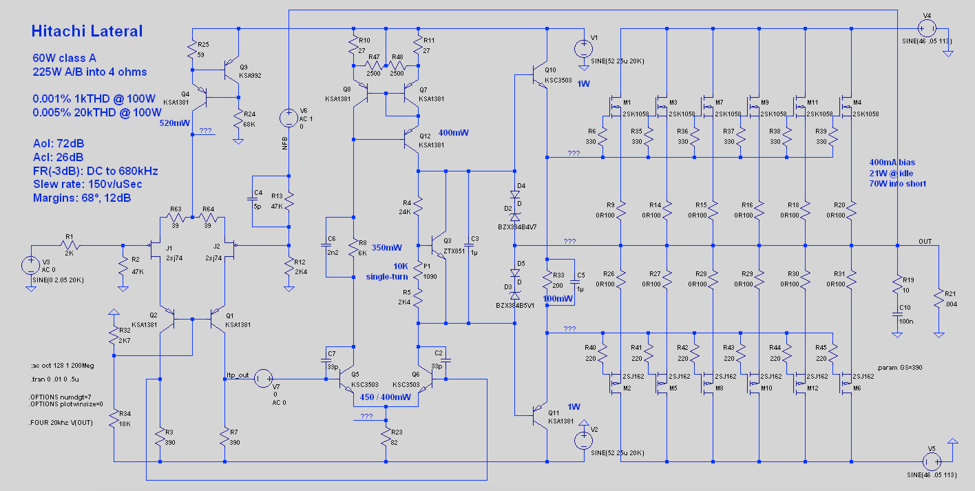
I've also done a version with vertical outputs. Topology (and board) are the same, with just a few value adjustments.
JamJar: an HPA-1-inspired power amp
Mine is upside-down from Keantoken's, but aside from that they even use the same transistor families!
I note the following differences:
1) I don't have the emitter-followers before the second LTP
2) I've got a bit more Miller comp, and a tiny bit of phase-lead comp in the NFB
3) I've moved the offset adjustment to the second LTP (Jam's idea)
4) I'm using a Wilson current mirror
5) I'm using a Vbe spreader for the bias
6) I have a speed-up capacitor between the drivers
7) I have no degeneration on my drivers
I've also done a version with vertical outputs. Topology (and board) are the same, with just a few value adjustments.
JamJar: an HPA-1-inspired power amp
Attachments
Nice one Jeff. Goldmund upside down ")
For those who doesn't have a bunch of SJ74's I belive that one could turn IPS and VAS around and use 2 x 2SK2145 or 4 x 2SK209 instead
I read a bit in your thread. Regarding Wilson CM I can say that I was very confused when building Cubie 3 as a newbie with KSA1381/KSC3503 in combination with BC5X6.
Could'nt get it to work at all, but swapped out 1381/3503 for 1220/2690 instead, wich worked great.
I had suddenley learned about Earley
/Figge
For those who doesn't have a bunch of SJ74's I belive that one could turn IPS and VAS around and use 2 x 2SK2145 or 4 x 2SK209 instead
I read a bit in your thread. Regarding Wilson CM I can say that I was very confused when building Cubie 3 as a newbie with KSA1381/KSC3503 in combination with BC5X6.
Could'nt get it to work at all, but swapped out 1381/3503 for 1220/2690 instead, wich worked great.
I had suddenley learned about Earley
Code:
/Figge
I noticed one of the schematics posted here specified a shunt-regulated front-end. I did a couple of shunt-reg designs in the Jam Jar thread but in the end gave up due to heat issues with wide line voltage variation.
I ended up with a discrete series regulator which has decent attenuation and stellar output impedance. Most importantly, it's simple enough that I can understand it.

I ended up with a discrete series regulator which has decent attenuation and stellar output impedance. Most importantly, it's simple enough that I can understand it.
Attachments
This is a thread I opened to get suggestions for low current, high voltage supplies to use on a Luxman clone I'm building.
This might be the best option, but it has a capacitance multiplier at the input.
Using the LM317 with higher voltages
There's an LTSPice file enclosed there.
This might be the best option, but it has a capacitance multiplier at the input.
Using the LM317 with higher voltages
There's an LTSPice file enclosed there.
I played around with it a bit in LTSpice here: JamJar: an HPA-1-inspired power amp (link should go to post 388).
I ran into a couple of issues: some of the more linear pucks are prone to hot-spots with higher rail voltages. (Although there is a post in that thread where 2_picoDumbs lists some of them that aren't.)
I played around a bit with cascoding, but I think the real answer is to run an X, which I'm not quite ready to tackle. That and I already have 30 SK1058s and 30 SJ162s.
here's one version from an old databook:
https://storycase.co.uk/radio/wp-content/uploads/2017/05/HitachiMosFets.pdf
there are others that I'm sure other folks will chime in with.
the "original" version that I've seen was the write-up in the IEEE Consumer Transactions technical journal back sometime around 1977 (?) that introduced lateral mosfets. I've never seen that as a download - I saw it first in college in the engineering library.
mlloyd1
ok, here's the whole data book including a later version of the app note from the databook above:
1985_D11_Hitachi_Power_MOSFET_Data_Book 1985 D11 Hitachi Power MOSFET Data Book
I'm done for the night now ...
Last edited:
It’s probably been mentioned here, but using a ferrite on the gate pins of the outputs is a very good thing, was used on the original Goldmund for a good reason, and is also suggested in the Profusion application guide.
Having decent results from some Fair-Rite type 43 parts.
Having decent results from some Fair-Rite type 43 parts.
Bought these mono blocks: T300 Copy/Study Goldmund Telos 300 Power Amplifier Mono Block Power amplifier 200W*2@8ohm 400W*2@4ohm|Amplifier| - AliExpress
Let's see how they sound.
Here's the schematic, I haven't compared it yet fully to the original(s) to see are there any changes. Is the trimpot W2 and Q11 additions to original schematic and do they adjust bias of the output stage or DC balance (and the 820R resistors adjust bias)? Also the last gate resistors marked 1000R instead of 100R, misprint or real and why?
How high bias would be adviseable without knowing how closely the mosfets are matched without risking thermal runaway, and what is the "original" value per mosfet usually in goldmunds?
I will replace the fuses with small resistors and measure the voltage drop across them, but it wont tell how much current each of them hogs.
I will replace the fuses with small resistors and measure the voltage drop across them, but it wont tell how much current each of them hogs.
How high bias would be adviseable without knowing how closely the mosfets are matched without risking thermal runaway
As these are laterals thermal runaway is not an issue. The max bias will be limited by heatsink size. The outputs better be matched if high power or work in low impedance loads is important.
Bought these mono blocks: T300 Copy/Study Goldmund Telos 300 Power Amplifier Mono Block Power amplifier 200W*2@8ohm 400W*2@4ohm|Amplifier| - AliExpress
Let's see how they sound.
Here's the schematic, I haven't compared it yet fully to the original(s) to see are there any changes. Is the trimpot W2 and Q11 additions to original schematic and do they adjust bias of the output stage or DC balance (and the 820R resistors adjust bias)? Also the last gate resistors marked 1000R instead of 100R, misprint or real and why?
They sound very good, like 10k amps compared to my EAW CAZ1400 pro-amp. Very pure, authoritative sound and large sound field which reminds me of tube amps. Clever inner construction also, rectifier and some other psu-related stuff resides in a separate aluminum cover under the power transformer. Non-magnetic screws everywhere except the psu caps (which I changed to brass), attention to details is high level.

They have changed the schematic quite much. The 4 zener diodes have gone, and only two small compensation caps. Also have added 0,25R drain resistors for output transistors current sharing. This is far from original Goldmund schematic, but Goldmund inspired.
To my disapontment they have also added the 220uf/16V Elna Cerafine (in the middle of the board) in series with the 330R resistor (R12 in schematic) in the feedback loop which makes the amp AC-coupled.
I'm quessing I can just short the Elna caps to make the amp DC-coupled again?
Yes remove the cap, but you should thermally couple the input differential pair to reduce the DC offset drift. The gain of a power amp is higher than a line stage preamp so a dc servo would be a lesser evil, but hard to retrofit to an existing pc board ( there were a few dc servos psc boards on ebay)
I actually had this in my mind. Do the other transistor pairs benefit from better thermal coupling also?
I have bought some mu-metal foil (ultraperm 80), some copper tape with conductive glue, thermally conductive glue and 8mm inner diameter plastic caps which I intended to use to make a "hats" for the transistor pair/-s that fully enclose them in same air space. The sandwitch of the foil shields conductive/ferromagnetic/conductive layers protect them good electromagnetically and also electrostatically if I ground the shield.
Some pair ran quite hot, was very hot to touch. Only concern is will they run hotter if there is a plastic layer separating the thermal glue and metal foils or should I drill a hole to the top of the cups that allows direct contact between the thermal glue and the metal foils for better dissipation.
Last edited:
- Home
- Amplifiers
- Solid State
- Goldmund Mods, Improvements, Stability