This is a PM I sent to another member. Some of you have given me a lot of help to get this project done, so I intend to finish it eventually (thanks!). However it would be a disservice to the project to rush into things, so I would like to take some time to get used to prototyping and troubleshooting real circuits.
keantoken said:Hello.
I have not been able to put the circuit together yet.
I started this project but I didn't really have the ability to complete it immediately.
I graduated from HS on the 4th, so I have more time on my hands now. After I have done some experimenting on real circuits, not just simulations, I will probably make some amendments to the circuit and then build it.
I regret that I haven't done anything in a reasonable amount of time but I don't feel very good about leaving this project after so many showed interest and helped me along. So it will be done. However I must take this slowly, since electronics isn't the only thing on my mind, and economy troubles, yada yada.
Please be patient,
- keantoken

I've discovered that masking tape will do fine for my new style of groundplane prototyping:
http://www.diyaudio.com/forums/solid-state/190115-ground-plane-prototyping.html
I've learned that the 2SC5171/SA1930 Toshiba datasheets are are loaded, they are nothing like the real devices. It is better to use the 2SC4793/SA1830, which are actually about as good as the datasheets suggest.
I think signal ground will just be a wire suspended above the board, away from the ground plane.
With this kind of construction I will be able to use one board for both channels, assuming I have a compatible heatsink.
- keantoken
Hi
Do you have the lastest schematic of the goldmund amp with 2SK1058 ?
thanks
this topic is closed
http://www.diyaudio.com/forums/soli...mimesis-3-clone-worlds-best-amplifier-13.html
Do you have the lastest schematic of the goldmund amp with 2SK1058 ?
thanks
this topic is closed
http://www.diyaudio.com/forums/soli...mimesis-3-clone-worlds-best-amplifier-13.html
It's probably been discussed before in this thread but it's late and I don't want to read through it at this time!
For the driver stage if it's low current draw I thinking just implement a regulated voltage doubler circuit like the original. There's nothing really wrong with doing this right?
For the driver stage if it's low current draw I thinking just implement a regulated voltage doubler circuit like the original. There's nothing really wrong with doing this right?
That schematic lacks a miller compensation cap for some reason, and will surely oscillate. Furthermore, the values are unrefined since it has never been tested. Base and gate stoppers should be optimized, as well as the output zobel, driver stage bias current, and pretty much all other operating points. Degeneration should also be optimized. This should be done by someone with a good signal generator, fast oscilloscope, and good speakers.
Also, I don't know if Digora means the schematic for my design, he may be meaning a different schematic.
I will get to this in the future, believe it or not. I still have all the stuff I've been sent.
- keantoken
Also, I don't know if Digora means the schematic for my design, he may be meaning a different schematic.
I will get to this in the future, believe it or not. I still have all the stuff I've been sent.
- keantoken
Goldmund module A1 modify to A2
Hi All,
Adapted from NagysAudio how Goldmund A1 module modify to A2 version :
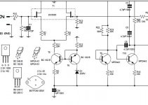
2.) On T6 (the now new MPSA42), short C-B instead of E-B. This can be easily accomplished without any modifications to the PCB. BC182B's leg pin out is CBE and MPSA42's leg pin out is EBC. Simply solder in the new transistor facing the same way.
According to my enclosed circuit , if follow above changing, I think the T6 will completely reverse the polority so the collector will via R12 going to GND. Does it work ?
CK
Hi All,
Adapted from NagysAudio how Goldmund A1 module modify to A2 version :
2.) On T6 (the now new MPSA42), short C-B instead of E-B. This can be easily accomplished without any modifications to the PCB. BC182B's leg pin out is CBE and MPSA42's leg pin out is EBC. Simply solder in the new transistor facing the same way.
According to my enclosed circuit , if follow above changing, I think the T6 will completely reverse the polority so the collector will via R12 going to GND. Does it work ?
CK
Attachments

I made amplifier here, invite you to see:
http://www.diyaudio.com/forums/solid-state/243901-keantoken-h-amplifiers.html#post3661370
http://www.diyaudio.com/forums/solid-state/243901-keantoken-h-amplifiers.html#post3661370
HI
Someone could help me adapt the values of the "original" goldmund amp to use 2SK170BL 8mA or 2sk246 Y with 25V AC transformer ?
https://sites.google.com/site/opampbasedamp/TELOS_L.asc
I also have 2sk389BL, but not compatible with the PCB :
https://sites.google.com/site/opampbasedamp/GM.JPG
https://sites.google.com/site/opampbasedamp/GM.pdf
thanks
Last edited:
Hi all,
It's 2017 now, I collected some materials and plan to make it wiki-like. Here's the new build thread.
http://www.diyaudio.com/forums/solid-state/304699-goldmund-wiki-build-2017-a.html
best,
Eric
It's 2017 now, I collected some materials and plan to make it wiki-like. Here's the new build thread.
http://www.diyaudio.com/forums/solid-state/304699-goldmund-wiki-build-2017-a.html
best,
Eric
Last edited:
- Home
- Amplifiers
- Solid State
- Goldmund Mods, Improvements, Stability