The stator pics are from some panels completed in 2009. They were used for experiments to validate segmented stator line source theories and models mentioned in many threads on this forum. They are retired from testing duties, now happily playing music instead of being tortured with test tones.
Hi Bolserst,
Could you please share some details of your build :
a) What is the size of each of three sections of the speaker?
b) Did you use heat shrinking only?
c) What's the fundamental resonance of whole panel ?
d) Are there any particular reasons you have chosen symmetrical sections?
Regards,
Lukas.
Could you please share some details of your build :
a) What is the size of each of three sections of the speaker?
b) Did you use heat shrinking only?
c) What's the fundamental resonance of whole panel ?
d) Are there any particular reasons you have chosen symmetrical sections?
Apologies for the tardy reply…am away from home on business.
a) The ESL Panel was divided into 3 sections (3.25” x 64”) = (8.25cm x 163cm)
b) The diaphragm was stretched lightly to remove wrinkles before attaching to fame. Then heat shrinking was used to define final diaphragm tension.
c) Resonance of all 3 sections is 80Hz. This drops to about 73Hz when the bias supply is turned on due to the negative compliance terms in the force equations for a constant charge ESL.
d) The width of the 3 sections was chosen to achieve the desired 70 – 75Hz resonance. When resonance is damped to Q=2.5 it provides flat response down to 80Hz WITHOUT the usual mid bass suck-out seen in most full range ESLs. Also, selecting this resonance frequency and damping allows the panels to be driven hard playing any type of music without concern for the diaphragm hitting the stators.
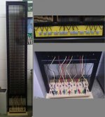
Note that although the panel was divided physically into 3 sections for diaphragm resonance concerns it is divided electrically into 13 sections for equalization of the line source response and improved dispersion at high frequencies. I have a few cell phone pics where you can see the electrical segmentation. Not the best quality, but should give you the idea. Note the bread board at the bottom of the ESL with wires from each section dangling down. I used this when experimenting with segmentation and comparing with theory …made it very easy to change resistor values or segment size to test different configurations. Once all experimentation was complete, I mounted resistors on a small board.
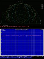
The current segmentation resistor values were tweaked slightly from theory to account for transformer parasitics, diaphragm mass, stator transparency, and baffle edges. The un-smoothed on-axis response shows what is achievable with resistor ladder driven ESLs. Polar data shows off-axis response to be well behaved with smoothly increasing directivity and no lobing.
Attachments
I used this glue on my welding rod / plastic grid stators. It's a 1-part solvent dry glue that sets to a hard elastic consistency. I haven't tried it on PVC but I can tell you it sticks like you wouldn't believe to polycarbonate & styrene plastics, metal and wood.
E6000 glue
E6000 glue
Apologies for the tardy reply…am away from home on business.
a) The ESL Panel was divided into 3 sections (3.25” x 64”) = (8.25cm x 163cm)
b) The diaphragm was stretched lightly to remove wrinkles before attaching to fame. Then heat shrinking was used to define final diaphragm tension.
c) Resonance of all 3 sections is 80Hz. This drops to about 73Hz when the bias supply is turned on due to the negative compliance terms in the force equations for a constant charge ESL.
d) The width of the 3 sections was chosen to achieve the desired 70 – 75Hz resonance. When resonance is damped to Q=2.5 it provides flat response down to 80Hz WITHOUT the usual mid bass suck-out seen in most full range ESLs. Also, selecting this resonance frequency and damping allows the panels to be driven hard playing any type of music without concern for the diaphragm hitting the stators.
Note that although the panel was divided physically into 3 sections for diaphragm resonance concerns it is divided electrically into 13 sections for equalization of the line source response and improved dispersion at high frequencies. I have a few cell phone pics where you can see the electrical segmentation. Not the best quality, but should give you the idea. Note the bread board at the bottom of the ESL with wires from each section dangling down. I used this when experimenting with segmentation and comparing with theory …made it very easy to change resistor values or segment size to test different configurations. Once all experimentation was complete, I mounted resistors on a small board.
The current segmentation resistor values were tweaked slightly from theory to account for transformer parasitics, diaphragm mass, stator transparency, and baffle edges. The un-smoothed on-axis response shows what is achievable with resistor ladder driven ESLs. Polar data shows off-axis response to be well behaved with smoothly increasing directivity and no lobing.
Bolserst, you continually blow me away with your ingenuity. I was thinking that each wire group had to be the same size but I see yours are not.
My only computer with Excel crapped out so I can't at the moment check to see if your spread sheet accommodates different sized wire groups.
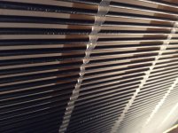
Correct me if I'm wrong but I count in your photo 13 wire groups which appear to be electrically segmented 7 groups; consisting of an 8-wire center group with paired groups of 4, 5,5,6,6 & 10 wires on either side.
Question: Does your spread sheet accommodate different sized wire groups?
Last edited:
No, the Excel spreadsheet calculator I posted does not accommodate different segment widths(ie wire groups). It was intended as a simple utility to help people understand the achievable results based on segmentation analysis in golfnut’s AES paper without having to understand all the math. I do have another spreadsheet calculator that does accommodate different segment widths as well as a host of other things like diaphragm mass, transformer parasitics, finite length of line, etc. It is the one I use to create the colorful polar plots you have seen in other threads....I was thinking that each wire group had to be the same size but I see yours are not... Does your spread sheet accommodate different sized wire groups?
Segmented ESL Polar Plot Comparions
Unfortunately it requires macros and is not exactly user friendly at this time. It is a backburner project to get it cleaned up to where typical DIY builder could use it with confidence, but I wouldn’t expect it anytime soon.
In the meantime, you can use the esl_seg_ui calculator to investigate the use of different segment widths.
Let me know if you are having trouble understanding the use of esl_seg_ui, and I can post an example starting with the results of the simple Excel calculator as inputs, and then modifying with different segment widths.
http://www.diyaudio.com/forums/plan...r-esl-simulator-esl_seg_ui-8.html#post3960276
Concerning the use of increasing segment widths:
There is no electrical or acoustic advantage to increasing the width of the segments as you work outward on the ESL panel.
At best, you can approach the performance of uniformly segmented panel.
Soooo...why did I do it?
1) To Simplify build since you have fewer segments and resistors to deal with. The tradeoff is that the calculations of the correct resistor values for each segment is more difficult.
2) To compare polar response and listening impressions with uniformly segmented panel of the same size.
3) Validate my modeling tools.
Last edited:
@ Bolsert, one question how did you manage to strecth all the wires so far like they did in the audiostatics ?so they stay straight when tension is released, i tried once but the forces on so much wires are pretty insane. i thought about making a jig that can stretch 8 at one time to devide the tension a bit?
It's true, it requires a LOT of force to straight all the wires at once. But it can be done and certainly makes construction easier and much more consistent. I used a metal frame with sliding end blocks with pins that can be moved with threaded rods or something similar. With greased threads and sliding surfaces, it wasn't that difficult to generate the required force to stretch all the wires at once.@ Bolsert, one question how did you manage to strecth all the wires so far like they did in the audiostatics ?so they stay straight when tension is released, i tried once but the forces on so much wires are pretty insane.
Some details, pics, and links on this topic here:
Stator Wire Stretching Rigs
Building my second ESL 's, I have used this strategy for the first time:
I use solid core copper wire with PVC insulation. The core is 1.5 millimeter in diameter and including insulation about 2.7 mm. I don't have a stretching jigg but use an electric drill to rotate the copper wire and simulaneously pull resulting in a perfectly straight wire.
For glueing I use hot glue which I think is great. The advantage is that it hardens very quickly enabling me to quickly assemble the stator. The problem is that the glue protrudes way too much. I solve this by applying an hot iron on the bead of glue with a piece of baking paper in between. When the glue starts to melt again I remove the hot iron and gently move a piece of straight plastic over the baking paper which covers the soft bead in the direction of the wires. This results in a perfect alignment of glue with the wires, without any protrusion. I have not been able to test this stator yet but it looks promising.
Attachments
Last edited:
Building my second ESL 's, I have used this strategy for the first time:
I use solid core copper wire with PVC insulation. The core is 1.5 millimeter in diameter and including insulation about 2.7 mm. I don't have a stretching jigg but use an electric drill to rotate the copper wire and simulaneously pull resulting in a perfectly straight wire.
For glueing I use hot glue which I think is great. The advantage is that it hardens very quickly enabling me to quickly assemble the stator. The problem is that the glue protrudes way too much. I solve this by applying an hot iron on the bead of glue with a piece of baking paper in between. When the glue starts to melt again I remove the hot iron and gently move a piece of straight plastic over the baking paper which covers the soft bead in the direction of the wires. This results in a perfect alignment of glue with the wires, without any protrusion. I have not been able to test this stator yet but it looks promising.
he thats funny i used that Technic as well
") be it with a heat gun then put a plastic strip with waxed paper on it and clamp it down. when its dry you remove the strip and got a perfect seem
be it with a heat gun then put a plastic strip with waxed paper on it and clamp it down. when its dry you remove the strip and got a perfect seemNo, the 406 does not require the use a primer for strong bond with PVC insulation.Did you use the primer with Loctite 406, or just the CA on its own?
The only surface prep done was cleaning the crossbars and stretched wires with alcohol.
Thanks!Impressive bolserst ! That FR and polar are stunning.
That is pretty much it…I suspect you have to stretch the wires till you take the metal into plastic deformation. Then can release most (but not all) of the tension before glueing but still have straight wires. Bolserst?

http://www.diyaudio.com/forums/plan...sl-project-file-translated-2.html#post2244928
CharlieM came up with a slightly different method where he could release essentially all of the tension, using thread rods to keep wires aligned where he wanted them.
http://www.diyaudio.com/forums/planars-exotics/287941-yet-another-segmented-esl-2.html#post4649057
Yep, seems to work pretty well. I am also going to try to use hot glue to attach the mylar membrane to a frame. First tests look promising, wonder if it will have a bond that's strong enough.
I have just used hot glue for attaching the mylar to a (composite) frame and it works perfectly. I put a thin bead of hot glue along the entire frame, then I loosely stretch the mylar over the frame. Then I place baking paper over the frame and apply a hot iron until the glue melts again. When the entire piece of mylar is glued, I stretch it using a heatgun.
There are two advantages over "normal" glue: 1. the glue hardens instantly speeding up the building process. 2. The mylar can be pulled off the glue quite easily, enabling you to quickly remove it and apply a new piece. The mylar is removed but the glue stays put on the frame. I burnt a hole in the mylar the first attempt of stretching with the heatgun but had a new setup in a matter of minutes.
Hope it will be of use to some
I used this glue on my welding rod / plastic grid stators. It's a 1-part solvent dry glue that sets to a hard elastic consistency. I haven't tried it on PVC but I can tell you it sticks like you wouldn't believe to polycarbonate & styrene plastics, metal and wood.
E6000 glue
Safety Info
http://eclecticproducts.com/downloads/tds-e6000-craft-english.pdf
http://www.hsia.org/applications/safe-handling-perc-drycleaning-solvent.pdf
I used the E6000 glue to attach the PVC insluated wires of my new wire panels. It works great... no problems.
- Status
- This old topic is closed. If you want to reopen this topic, contact a moderator using the "Report Post" button.
- Home
- Loudspeakers
- Planars & Exotics
- Glue for wire stators