Interesting, I have 13 of these (attachment).
These is no circle at pin 1 which makes it look like the pre TI picture.
The bottom says PHILS with a C04 in the middle.
Look like a May 2004 production.
The fact that the shiny pin 1 circle isn't on them doesn't necessarily mean they're fake. As I wrote before, looks can be deceiving.
More recent production (from ca. 2005/2006 on) seems to come from a factory in Thailand exclusively. But it's likely they were manufactured at more than one site previously, possibly even simultaneously. Those from a different factory might look different but still be legit. Ca. 2006 was the year our customer changed from AM to AP or BP for almost all products, so I didn't get to deal with 627APs/BPs before that, so they might have looked like your's all the time back then.
The items in your photo have a TI-style datecode, which would be logical as TI owns BB since, IIRC, 2000.
In old surplus stock at work I found some BB DRV134PAs, balanced line drivers used in professional AV-equipment. With the exception of a white BB logo and type, they look exactly like your OPA627APs.
The datecode, 15ZHQN7 (May 2001, not 2011), reveals two similarities with the one on your 627s. . The production site code is 7, which means they should be from the same factory as your 627AP's. Indeed they seem to be, the bottom says PHILS in the circle. All four DRV's have a different three letter/digit combination in the middle of the circle (F15, J02, J18 and L08). My guess is these are the numbers of the dies used for encasing, and obviously there would be quite a few.
The second thing of the datecode that strikes me is that all Thailand OPA627s have W as the first letter of the lotcode. We also use quite a few OPA350s and come from the same factory because the site code is B, and with them too every lot code starts with W. Perhaps W as first letter in the lot code can only be found in combination with B for the site code. The case of the 350s always look exactly like the 627's: half cirlce indent combined with shiny dished pin 1 circle.
Your 627APs have Z as the first letter of the lotcode, and lo and behold... the DRV's from the same factory do too. Perhaps Z is coupled to 7. If this is true, that would be another clue to recognize counterfeits by: the first letter in the lotcode combined with the wrong site code...
My bet is your 627s are genuine if quiescent current is approx 7 mA.
Last edited:
It is always fun to decipher the product code 
A couple years ago, I bought these 627AP (in a lot along with other parts) from a long time member who decided to quit DIY and to clear the last batch of parts. I also think these are genuine. Just curious, how to test the quiescent current? I would like to learn how to do so.
Thanks!!
A couple years ago, I bought these 627AP (in a lot along with other parts) from a long time member who decided to quit DIY and to clear the last batch of parts. I also think these are genuine. Just curious, how to test the quiescent current? I would like to learn how to do so.
Thanks!!
It is always fun to decipher the product code
A couple years ago, I bought these 627AP (in a lot along with other parts) from a long time member who decided to quit DIY and to clear the last batch of parts. I also think these are genuine. Just curious, how to test the quiescent current? I would like to learn how to do so.
Thanks!!
You want to know the current drawn by the internal opamp circuitry only without the current drawn by the load on the output.
Leaving in- and/or outputs floating is, however, not a good idea. The output of the opamp will go into positive or negative saturation immediately if there's no feedback. I found that this affects current draw by a few tenths of a mA.
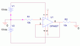
What you need is a stable circuit that doesn't deliver current into a load because the output = 0 V.
I chose to build a voltage follower (aka buffer) with 0 V in and therefore 0 V out.
You need:
symmetrical +/- 15 V power supply (PSU),
ammeter that can measure in the 0-40 mA, or 0-400 mA range.
two 10kOhm resistors,
wires and/or jumper leads
maybe also:
Veroboard
DIP-8 socket
I built the circuit on a breadboard, but you may also solder a socket and the other components on a Veroboard.
Here's how to wire the circuit:
Take a look at the pin configurations in the datasheet first.
1) Connect +15 V to pin 7 (+Vs)
2) Connect -15 V to pin 4 (-Vs)
3) Connect a jumper lead between pin 6 (Output) and pin 2 (-In)
4) Connect pin 6 (Output) with 10 kOhm to GND
5) Connect pin 3 (+In) with 10 kOhm to GND
Pins 1, 5 and 8 must be left unconnected.
I will post a schematic later.
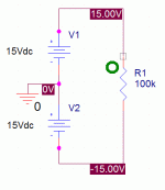
I assume you know how to connect the symmetrical PSU to your circuit. The ammeter can be connected in series with either of the PSUs.
If you doubt you built the circuit correctly, try it with a cheap pin-compatible opamp first (e.g. uA741) and compare measured value with the one in the datasheet.
The datasheet of the OPA627 specifies that the current drawn from a +/- 15V PSU is typically +/- 7 mA at 25 degrees C with a max. of +/- 7.5 mA.
That's what you should expect to measure on a genuine OPA627. Right now I have a OPA627AM in the test setup and it stabilizes (allow some warm-up) at 7.14 mA.
Last edited:
There may be no need to go out and buy a 7915.
If the transformer you plan to use has two fully separate secondary windings, you can build a symmetrical power supply with two 7815s. You'll end up with two +15 V PSU's that you can then wire in series to get a symmetrical PSU, just as you would do with an off the shelf dual laboratory PSU.
Circuit common (GND) will be where the two are connected in series. Measured with respect to that point, your DMM will read + and - 15 V.
First build two completely separate +15 V PSUs connected to each of the secondary windings. Only the outputs will be connected in series to become a symmetrical PSU.
The only differences in the needed parts to the usual setup are that you need two bridge rectifiers (instead of one) and two 7815s (instead of 7815+7915).
Attachments
poll closed, decision made
Back to the original topic.
The poll has closed and I have decided not to maintain and post a list of known genuine datecodes/lot trace codes. Mostly because of the low numer of voters and the outcome, but also because I'm beginning to suspect that the number of opamps sharing the same datecode might not be incredibly large in number...
Last edited:
The cans you can grind off and see what is inside. I am curious as to what they are if you could send a couple of fake cans I can return the favor with some ADI parts of your choice. Yes on the AD4627, though TI-BB has replaced the 627 on a more modern SOI process since the DI fab has or is going to be shut down eventually.
Sorry, I should not have expected folks to know SOI means silicon on insulator. The OP627 was made on dielectrically isolated wafers and AFAIK there are no 8" or larger wafers available, 6" wafers are just not economical anymore. Folks should at least try, for instance, the OPA827 very little ventured in the experiment.
If you compared the price and figured out how many are on a 12" wafer, you will see how sand is transmuted to gold
Last edited:
Do you happen to know when TI/BB switched to the more modern process?
The long leadtimes and problems showed up in 2007 when the switch started. Rather than provide mis-information I have a call into a designer that was there at the TI-BB merger and is now back here. He had a funny story about how much work he had to do to get his MAC to look like a PC on the network, TI is/was an Apple verboten house.
I managed to test the 4 OPA627AM, 8 OPA627BP (DIP) and a bunch of OPA627AU (SMT on DIP adapter) that I bought from my Shenzhen, China source, They all test between 7mA and 7.4mA. I did a bunch of listening test on my modded Marantz 63 compared to a couple of OPA627BP I had sampled from BB way back when. I thought actually I preferred the AUs over either the BPs (on single to dual adapter) or the AMs (on single to dual adapter and on top of another socket to clear the components). That could be due to the longer traces, inductances in the supply path etc. Whatever advantages I thougth people talked about BP or AM over the AU just were not apparent in that set up. The AUs were smoother and less shrill with more sound stage definition but the timbre was consistent across the types.
Sorry to take this thread a bit tangent.
Sorry to take this thread a bit tangent.
As far as I know the process has not changed. In my experience with many analog IC vendors, 'higher end' analog products don't get moved from process to process. The process might be moved to a different factory, but it's usually the same basic process. In general, the effort spent to exactly duplicate a product on a different process is more profitably spent to create a new/improved design and/or something totally different. It's a different story with NAND gates or maybe grunt 3-pin linear regulators...
As far as I know the process has not changed. In my experience with many analog IC vendors, 'higher end' analog products don't get moved from process to process. The process might be moved to a different factory, but it's usually the same basic process. In general, the effort spent to exactly duplicate a product on a different process is more profitably spent to create a new/improved design and/or something totally different. It's a different story with NAND gates or maybe grunt 3-pin linear regulators...
I thought people were trying to track down the date codes for parts made in the original Tuscon Burr Brown fab. In transfering lines there is rarely a perfect match, especially in things like thin film targets, etc. Personally the sonic differences are lost on me. In any case if you look at the data sheets the OPA827 is virtually a mirror image of the OPA627. The native JFET's are different flavors and the newer OPA827 has a simple diamond output (probably much higher ft's on their SiGe process).
For audio I don't see any reason not to give it a try. Tracking down artifacts at $20-$40 @ seems rather an excess.
I thought people were trying to track down the date codes for parts made in the original Tuscon Burr Brown fab.
That was not the reason why I started this thread. I started it because even brand new OPA627s cost $ 20-40 when bought from an authorized dealer. Obviously a high price like this is what keeps the counterfeiters interested in the OPA627.
In transfering lines there is rarely a perfect match, especially in things like thin film targets, etc. Personally the sonic differences are lost on me.
The reason I asked about the change in production process was because there seems to be more variation within the specs set down in the datasheet than before.
Let me explain. One of the products we produce for our customer is a differential amplifier, containing two OPA627s each. Obviously common mode rejection is an important feature in its design.
To make a long story short: nowadays we find that we have to match quite a few OPA627s to be able to adjust HF CMR to within the requirements set down by our customer. In the past 99 of 100 diffamps met requirements without matching, nowadays it's only half that. Since the design has remained the same for many years, I can only point to the OPA627s as the culprit. Perhaps a change in production process made this happen.
In any case if you look at the data sheets the OPA827 is virtually a mirror image of the OPA627. The native JFET's are different flavors and the newer OPA827 has a simple diamond output (probably much higher ft's on their SiGe process).
For audio I don't see any reason not to give it a try. Tracking down artifacts at $20-$40 @ seems rather an excess.
At home I enjoy a wonderful CD-player that that uses an OPA132 per channel for the output stage. They work so well in combination with the rest of the circuit that I wouldn't dream of changing them for '627s.
At work I deal with them so much that calling them "artifacts" sounds a bit strange to me. Makes it sound like these are rare things used for specialty applications only. Granted, we use them only for this one customer... in... indeed a specialty application...
Last edited:
That was not the reason why I started this thread. I started it because even brand new OPA627s cost $ 20-40 when bought from an authorized dealer. Obviously a high price like this is what keeps the counterfeiters interested in the OPA627.
The reason I asked about the change in production process was because there seems to be more variation within the specs set down in the datasheet than before.
Let me explain. One of the products we produce for our customer is a differential amplifier, containing two OPA627s each. Obviously common mode rejection is an important feature in its design.
To make a long story short: nowadays we find that we have to match quite a few OPA627s to be able to adjust HF CMR to within the requirements set down by our customer. In the past 99 of 100 diffamps met requirements without matching, nowadays it's only half that. Since the design has remained the same for many years, I can only point to the OPA627s as the culprit. Perhaps a change in production process made this happen.
At home I enjoy a wonderful CD-player that that uses an OPA132 per channel for the output stage. They work so well in combination with the rest of the circuit that I wouldn't dream of changing them for '627s.
At work I deal with them so much that calling them "artifacts" sounds a bit strange to me. Makes it sound like these are rare things used for specialty applications only. Granted, we use them only for this one customer... in... indeed a specialty application...
Never mind, I mis-understood this to be a DIY audio application. AFAIK the OPA827 was meant as a lower cost newer process version of the OPA627. From the specs and schematic it could very well be a drop-in for many/most of their customers. I am not talking about audio op-amp rolling. From my perspective op-amps at those prices are extremely unusual and are usually designed out ASAP.
Never mind, I mis-understood this to be a DIY audio application. AFAIK the OPA827 was meant as a lower cost newer process version of the OPA627.
Input bias current of the '827 is triple to tenfold that of the max. spec of the '627BM. That alone probably renders it useless for designs that need incredibly high input impedance. The instrument I'm talking about is specified at > 1T Ohm.
From the specs and schematic it could very well be a drop-in for many/most of their customers.
Agreed, for most applications it should do OK.
I am not talking about audio op-amp rolling. From my perspective op-amps at those prices are extremely unusual and are usually designed out ASAP.
Yes and no.
With certain industrial products, the "tried-and-tested" phenomenon is more important than using the newest technology or cheaper components. Markup of certain products is beyond belief (comparable to commercially sold high end audio), so there's not that much of an incentive to replace an OPA627 with something else that should do, like the ADA4627-1. Perhaps for new designs might the latter be considered and tested, but it's unlikeley it'll be done for existing designs.
That's not to say that nothing changes, I know of one redesign switching to the AD8610, which costs roughly a quarter of what the '627AU costs...
Input bias current of the '827 is triple to tenfold that of the max. spec of the '627BM. That alone probably renders it useless for designs that need incredibly high input impedance. The instrument I'm talking about is specified at > 1T Ohm.
A fine point, but they both have an specified input impedance of 10T Ohms and about the same ~8pF. Static Ib does not translate into input impedance. Both would rail with an actual T Ohm resistor on the input especially considering the Ib doubles every 10 degrees. Though it is true they were not able to get the Ib down as low, probably a process issue.
with something else that should do, like the ADA4627-1. Perhaps for new designs might the latter be considered and tested, but it's unlikeley it'll be done for existing designs.
That's not to say that nothing changes, I know of one redesign switching to the AD8610, which costs roughly a quarter of what the '627AU costs...
Cool, I've worked with both designers for 20yr.
A fine point, but they both have an specified input impedance of 10T Ohms and about the same ~8pF. Static Ib does not translate into input impedance.
The input impedance of the instrument is measured at DC by charging a small (10nF) low leakage cap to a certain voltage, stop charging, then measure what happens to that voltage during the next 5 minutes. Ideally it should remain constant, but in the real world that's not going to happen. Usually the graph (voltage vs. time) shows either a dropping or rising curve.
A drop or rise is the result of current leaking to negative rail, gnd or from positive rail. All pcbs with sensitive signals are washed after soldering because flux residue left by the soldering process will lead to excess leakage.
Both would rail with an actual T Ohm resistor on the input especially considering the Ib doubles every 10 degrees. Though it is true they were not able to get the Ib down as low, probably a process issue.
The rise in bias current with rise of temp might explain why we mostly see dropping curves in the summer while in the winter we often see rising curves.
I guess in this case input bias current probably can't be considered negligible.
I have been trying to find another method of wielding out counterfeit OPA627s.
So far taking a good look at the OPA627 combined with a measurement of the quiescent current is all that was available to me but I might have found a DIY friendly way that only requires a scope, a LM393 and some resistors and a cap.
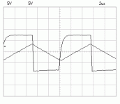
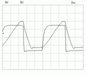
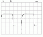
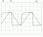
In the datasheet of the LM393 I found the schematic for a simple 100 kHz square wave generator. The output isn't a perfect square wave, but good enough.
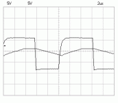
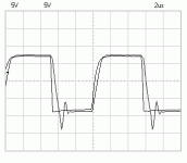
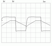
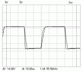
I built it on a breadboard and tried some different opamps in voltage follower configuration. That yielded some interesting results.
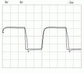
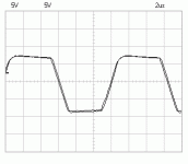
In the attachment you'll find the results in this order: left to right top: CA3160, NE5532, NJM4558, NJM4560, OPA627, left to right bottom: TL062, TL071, TL082, UA741 and LF411.
These are the opamps I have lying around. In- and output signals are overlayed.
Not all opamps could follow the 14 Vpp, 100 kHz output of the LM393 accurately. The CA3160, NE5532, TL082 and LF 411 seemed reasonbly capable. The NE5532 seemed to load the output of the LM393 a bit increasing rise- and falltime considerably.
The only opamp capable of following the input accurately was the OPA627, as you can see. Some cheap opamp masquerading as OPA627 probably won't be able to do that.
The LM393 was supplied with +15 V and GND, the opamps with +/- 15 V.
Attachments
-
 CA3160.gif5 KB · Views: 771
 -
 NE5532.gif4.8 KB · Views: 762
 -
 NJM4558.gif5 KB · Views: 755
 -
 TL062.gif5.3 KB · Views: 105
 -
 OPA627AP.gif4.8 KB · Views: 756
 -
 NJM4560.gif5.3 KB · Views: 748
 -
 TL071.gif4.8 KB · Views: 69
 -
 TL082.gif5.3 KB · Views: 65
 -
 UA741.gif4.9 KB · Views: 73
 -
 LF411.gif5.5 KB · Views: 76
Last edited:
- Status
- This old topic is closed. If you want to reopen this topic, contact a moderator using the "Report Post" button.
- Home
- Design & Build
- Parts
- genuine OPA627 info
