Earl,
The audibility SWAG offer is a target for you to shoot at. I will take a pass on that invitation.
Regards,
Bill
Actually it sounds like you being typically antagonistic. I already said that it was a guess on my part just as it would be for anybody else. If you are not here to discuss things then why are you here?
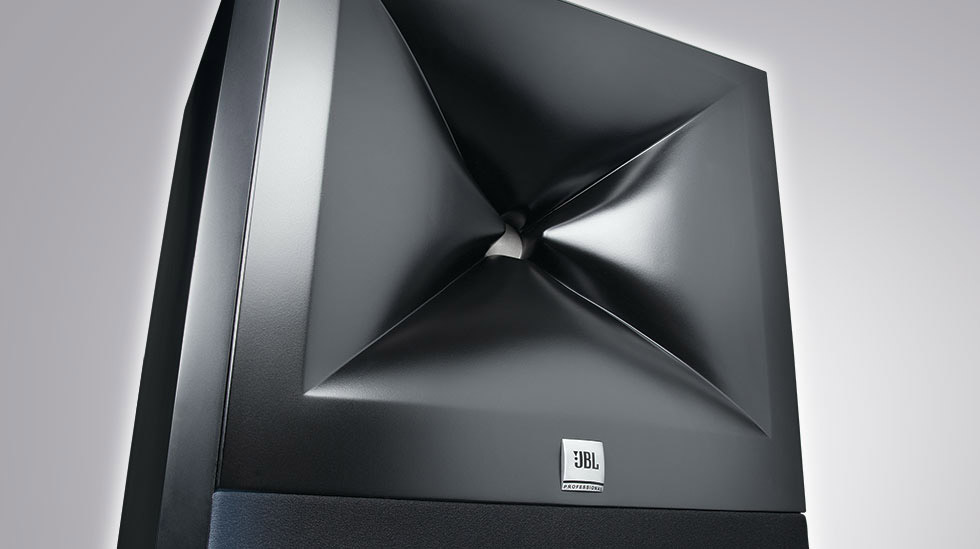
SWAG: Perhaps the wrinkled shape at the throat is intentionally designed to break up a planar wavefront, producing an incoherent wave by the time it emerges from the horn? Effectively, the horn analog of NHT's multiple-resonance transducer. As you mentioned, the exact opposite of a OSWG.
There's quite a lot of DSP in this system, which can smooth out the wrinkles, at least for the microphone's benefit.
This is exactly what I think as well and as far as I can tell from the patent it is supported by what is said. Mr. Sprinkle claims virtually any shape or location of various "perturbances", so it does seem like anything that perturbs the wavefront is fine. Exactly analogous to NHT versus Piston sources.
Target shooting already?
Antagonism is your mission, exemplified by yet an further rude question. If you throw down the gauntlet I will pick it up and engage you.
WHG
Actually it sounds like you being typically antagonistic. I already said that it was a guess on my part just as it would be for anybody else. If you are not here to discuss things then why are you here?
Antagonism is your mission, exemplified by yet an further rude question. If you throw down the gauntlet I will pick it up and engage you.
WHG
Pending Status
The international Search Authority more than agrees with you.
http://patentscope.wipo.int/search/docservicepdf_pct/id00000025593662.pdf
I was surprised to find this application under the mundane title "Loudspeaker Horn" not "Image Control Waveguide" OR just waveguide.
Regards,
WHG
If I'm reading it correctly, and I'm not at all convinced that I am, this patent would cover the preexisting QSC HPR152i waveguide? It has slight dimples, and seems like it meets the other criteria.
The international Search Authority more than agrees with you.
http://patentscope.wipo.int/search/docservicepdf_pct/id00000025593662.pdf
I was surprised to find this application under the mundane title "Loudspeaker Horn" not "Image Control Waveguide" OR just waveguide.
Regards,
WHG
Errata
Thanks for the post.
I was looking in the wrong place with the wrong search terms.
This patent application will most certainly be challenged further in its current form beyond that addressed by the Search Authority. There is known prior art, some of which is not even referenced therein.
I note that the implementation for the M2 Monitor is much more aggressive than that shown in the drawings.
I also notice that in the more recent 3-Series product releases, a diminution of the knuckle features has occurred, probably to reduce the amount of signal processing required and to accommodate the dome tweeter lodged in the horn throat.
Regards,
WHG
I think this is the one:
US2013020684 LOUDSPEAKER HORN
Thanks for the post.
I was looking in the wrong place with the wrong search terms.
This patent application will most certainly be challenged further in its current form beyond that addressed by the Search Authority. There is known prior art, some of which is not even referenced therein.
I note that the implementation for the M2 Monitor is much more aggressive than that shown in the drawings.
I also notice that in the more recent 3-Series product releases, a diminution of the knuckle features has occurred, probably to reduce the amount of signal processing required and to accommodate the dome tweeter lodged in the horn throat.
Regards,
WHG
Hi whgeiger,
Thank You and member POS to help us to try to understand more about M2 unusual horn shape. Unfortunately reading the mentioned patent application I have not find any specific technical information that would be a base of the M2 way of operation. So, up to now, I would remain in belief that K-tube like V-shape Karlson-coupler is the basic idea with 3D shaped reflecting surface, providing wide frequency dispersion off-axis.
If You remember, a kind of reflective surface to enhance the frequency dispersion has been applied to the JBL Paragon box to spread VHF signal, here (M2) K-coupler "allow" wide frequency range to be 'taken out off the central tube'.
Regards
ivica
I wonder what the flare rate is.
I think it is similar to the JBL 2344, with an hypex flare near the throat transitioning to a conical flare after the slot.
In the 2344 the rapid expansion in the vertical plan was "compensated" by the narrowing the the horizontal one, up to the slot.
Here the rapid extension seems to be in the obliques, like a mirrored 2344, with 4 smaller "butts" instead of the 2 big ones...
Last edited:
Looks like JBL has always been OK with horn diffraction, all the way back to the JBL horn-lens of the Fifties, through the Bi-Radial, and now the M2. Not that Altec was any better; the 511 and 811 sectoral horns, with the throat pinch, followed by the Manta-Ray horns of the Seventies.
Dr. Geddes' OSWG appears to be the first horn (or waveguide) specifically designed to lower diffraction, instead of intentionally increasing it with various kinks and folds in the throat and mid-throat region.
Dr. Geddes' OSWG appears to be the first horn (or waveguide) specifically designed to lower diffraction, instead of intentionally increasing it with various kinks and folds in the throat and mid-throat region.
Last edited:
Looks like JBL has always been OK with horn diffraction, all the way back to the JBL horn-lens of the Fifties, through the Bi-Radial, and now the M2. Not that Altec was any better; the 511 and 811 sectoral horns, with the throat pinch, followed by the Manta-Ray horns of the Seventies.
Dr. Geddes' OSWG appears to be the first horn (or waveguide) specifically designed to lower diffraction, instead of intentionally increasing it with various kinks and folds in the throat and mid-throat region.
Interesting for me: using OSWG, and if the expectable off-axis angle is about 45 deg, it is quite visible that the angular increment of the horn-wall is relative fast near the horn-throat, and as I understand such would not produce diffraction, so why not to use the same 'principle' on the horn mouth.
regards
ivica
Dr. Geddes' OSWG appears to be the first horn (or waveguide) specifically designed to lower diffraction, instead of intentionally increasing it with various kinks and folds in the throat and mid-throat region.
Lower diffraction was a stated goal at the very beginning. I had JBL diffraction horns in my system at the time. They were the weak point.
Diffraction Revisited Briefly
a) If the surface has curvature that recedes away from the direction of propagation then ......
b) If an edge (feature with dimensions << wavelength) is presented then ......
Regards,
WHG
Interesting for me: using OSWG, and if the expectable off-axis angle is about 45 deg, it is quite visible that the angular increment of the horn-wall is relative fast near the horn-throat, and as I understand such would not produce diffraction, so why not to use the same 'principle' on the horn mouth.
regards
ivica
a) If the surface has curvature that recedes away from the direction of propagation then ......
b) If an edge (feature with dimensions << wavelength) is presented then ......
Regards,
WHG
Attachments

The idea is to smear the results.
Is this what the reticulated foam, in a more subtle (or more widely distributed) way does for HOMs?
Sheldon
Is this what the reticulated foam, in a more subtle (or more widely distributed) way does for HOMs?
Sheldon
Yes, there would be some minor scattering, but the major effect is absorption. The fact that there is a hole on axis means that the wavefront is still quite coherent.
I'll take a stab at this ... the incident shadow boundary can be represented as a straight line along it's point of incidence with the sources transmission. Lining up at a third point in space (beyond the incident point) puts your "eye" on the boundary when the source, the diffraction point and your eye are in alignment. The incidence shape makes this possible.post7113
what is the difference between Incident Shadow Boundary and Surface Shadow Boundary?
The shadows boundary is less precise and it's boundary path will be dependent on the curved surface of the incidence. The curved incidence shape makes the actual point of incidence less defined.
To me and my understanding, it would be the radius of the curve that would define the shadow boundary. Since there is no clear incidence the shadow boundary will bend along the radius.They both diffract and both have a shadow boundary defined in the exact same way. The only difference is the radius of curvature of the two different edges.
To me the two boundaries are the same thing with different parameters. One edge is sharp and one not so sharp. They both diffract and both have a shadow boundary defined in the exact same way. The only difference is the radius of curvature of the two different edges.
As I understand, smaller the radius wider the diffraction area.
regards
ivica
- Home
- Loudspeakers
- Multi-Way
- Geddes on Waveguides