As far I can have some results with shape of the horn
as we discussed here past 2-3 pages...
.
This is with corrected parameters, suggested by GL and for ka=fib. num(1.6xxx), r rounded is lambda/8, etc etc...
just like example of shape.
.
I will later extract "leave" for cutting clishe.
And off course post here the math and results")
.
as we discussed here past 2-3 pages...
.
This is with corrected parameters, suggested by GL and for ka=fib. num(1.6xxx), r rounded is lambda/8, etc etc...
just like example of shape.
.
I will later extract "leave" for cutting clishe.
And off course post here the math and results
.
Attachments
Zoran,
I agree that plaster can be a little bit messy but is is an excellent way to make a model that you can use as a pattern. It can be done rather simply with a center core of many materials and turning the core about a centerline with a simple outer template making the final shape. Something else you could consider if you have a wood working shop around is to have the shape turned on a lathe out of something like a blank of Spruce or some local stable wood you may have in your area.I have made some very nice wooden horns from mahogany which looks nice by stacking blocks and carving the shape. You can make a center hole and place a pattern on each side of the cross section at that point and cut out the smaller shape and then hand shape the contour between the two points. I usually make sure to go through three points at a time and then you can make a very accurate shape. The thinner the sections the more accurate the shape change. The fact that the oblate spheroid has a large portion of the shape conic make this very easy to do.
good luck with your project.
Molding with plaster, when You have some experience, not necessary messy.
It could be done, for these sizes of pieces, even at home table.
And as I said it is "green" if You apply light protect hand skin with some cosmetics
.
aplying the shape is relatively easy - rotating half or whole section of horn around the center. And it is even easier if the model is from clay...
.
(I know this well because i am teacher at the academy of art...)
.
But after the making clishe, it is. Because of the synthetic materials for filling the mold
Maybe paper-mache technique is something to think about, but anyway it should be
retouched or cover with some "chemistry".
Which is not the such a problem until gas mask and proper measures applying with work.
Zoran,
I have worked as a pattern maker in an aerospace company and have literally used toms of plaster. It wasn't a standard plaster but was a tooling grade low shrink material we call Hydrocal. Fiberglass is a simple material to use to make the horn flare itself but as you say it isn't something that most people want to deal with. I did a lot of that and mostly with epoxy resins, sometimes with polyester but that shrinks to much for the precision work that I did most of the time. Most of my patterns had to be within a few thousandths of an inch so low shrink plaster was a requirement. It can get tricky when you have to allow for multiple shrinkage between multiple materials and getting a final part to print. Of course for audio none of this is important.
I have worked as a pattern maker in an aerospace company and have literally used toms of plaster. It wasn't a standard plaster but was a tooling grade low shrink material we call Hydrocal. Fiberglass is a simple material to use to make the horn flare itself but as you say it isn't something that most people want to deal with. I did a lot of that and mostly with epoxy resins, sometimes with polyester but that shrinks to much for the precision work that I did most of the time. Most of my patterns had to be within a few thousandths of an inch so low shrink plaster was a requirement. It can get tricky when you have to allow for multiple shrinkage between multiple materials and getting a final part to print. Of course for audio none of this is important.
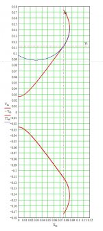
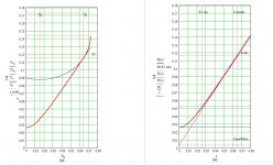
Hi this is example of horn
in zip file is mcd MathCad sheet.
with notes...
.
Hi Zoran,
I only wonder myself, when using such "fast flaring" horn (here expectable dispersion angle about 60 deg off-axis) especially when applied to 2" driver that has internally built-in "slow flaring" short horn what kind of diffraction would happen around horn throat.
May be a kind of QT-WG (Peavey Electronics Corporation) 'circular' curve in the throat would produce 'softer' horn-to horn transition.
More details in the US Patent: US6059069
Regards
ivica
Attachments
Last edited:
Thankss for the info
I dont use compression unit for this horn
and it is not rectangular rather circular because of forming shape from 24 pieces of "leaves", like old gramophones style...
(pretty much tend to circle...)
on the second pic is one piece of leaves, glued together will give the shape from the pic 1
I dont use compression unit for this horn
and it is not rectangular rather circular because of forming shape from 24 pieces of "leaves", like old gramophones style...
(pretty much tend to circle...)
on the second pic is one piece of leaves, glued together will give the shape from the pic 1
Thankss for the info
I dont use compression unit for this horn
and it is not rectangular rather circular because of forming shape from 24 pieces of "leaves", like old gramophones style...
(pretty much tend to circle...)
on the second pic is one piece of leaves, glued together will give the shape from the pic 1
Hi Zoran,
I think the shape is not important, as Your form is almost circular.
Not using compression driver but something else ( as an example D54), You have to be aware that the "cone" (or dome) must have enough stiffness concerning the horn loading.....but i believe that You have good experience with the driver You decide to use.
Regards
Ivica
Hi Zoran,
I only wonder myself, when using such "fast flaring" horn (here expectable dispersion angle about 60 deg off-axis) especially when applied to 2" driver that has internally built-in "slow flaring" short horn what kind of diffraction would happen around horn throat.
May be a kind of QT-WG (Peavey Electronics Corporation) 'circular' curve in the throat would produce 'softer' horn-to horn transition.
A wider waveguide will have HOMs at a much lower frequency, which are in essence the higher amount of diffraction at the throat. The QT would be worse in this regard than an OS. The QT was "invented" simply because at the time Charley Hughes could not draw an OS contour in his drawing package so he just used a "fillet". Basically it is a compromise to the OS and the OS should always be used if at all possible.
A wider waveguide will have HOMs at a much lower frequency, which are in essence the higher amount of diffraction at the throat. The QT would be worse in this regard than an OS. The QT was "invented" simply because at the time Charley Hughes could not draw an OS contour in his drawing package so he just used a "fillet". Basically it is a compromise to the OS and the OS should always be used if at all possible.
Hi Gedlee,
Does that mean that it would not be good to "insist on" the wider horn dispersion over say 30 ~ 45 deg off-axis dispersion?
That is an opposite way then nowadays leading flag in the "small horn" wide frequency JBL M2 horn suggest. Does that mean that at the JBL, while designing M2 horn the payed less their attention on the HOMs in order to allow 60 deg off-axis dispersion at very high frequency (over 15kHz)?
Interestingly for me is that OSWG is based on the quite different philosophy then JMMLC design suggestion. Does that mean that such design ( I can call it almost constant angular increment of the horn walls) would emphasize HOMs and diffraction?
Regards
Ivica
Maybe "insist" is too strong a word, but prefer is certainly the case. From my work 45 degrees seems to be the sweet spot. Wider has more HOM but narrower becomes too long and hard to package.
I cannot comment on what JBL engineers are doing. I don't do things the same way. My reasons are clearly stated by me and supported with measurements. I have not seen comparable measurements of the M2 horn.
The OSWG and the JMMLC are indeed quite different. The OSWG will have the lowest HOMs of any shape. The JMMLC is also not a constant directivity device. Its designer claimed that wasn't important. We obviously had different goals in mind.
Maybe "insist" is too strong a word, but prefer is certainly the case. From my work 45 degrees seems to be the sweet spot. Wider has more HOM but narrower becomes too long and hard to package.
I cannot comment on what JBL engineers are doing. I don't do things the same way. My reasons are clearly stated by me and supported with measurements. I have not seen comparable measurements of the M2 horn.
The OSWG and the JMMLC are indeed quite different. The OSWG will have the lowest HOMs of any shape. The JMMLC is also not a constant directivity device. Its designer claimed that wasn't important. We obviously had different goals in mind.
Hi Gedlee,
Sorry for my bad English, but I want to say that it seems to me that 30 to 45 degs off axis dispersio would produce good results, so may be Zoran would reduce his horn angle too,as it seems to that he is going too wide.
Yes, I know that JmmLC horns fir T <1 are not CD type. With larger T (in the horn flare equation) it starts to become less directional an "more " CD looking, but under such T the initial "starting" horn wall angle in the throat become too high, as i proportional to T and fo.
I believe that You have done a lot of measurement of different type of horns, that is the reason to ask if any info -not marketing one, You may have about new JbL M2 horn.
Thank You for the reply.
Regards
Ivica
Last edited:
Fusion
The curvature of the JMLC horn increases proportionally as the wave front travels down and along the horn boundary. So as pressure is decreasing curvature is increasing. This is the ideal condition for a horn mouth that minimizes reflectance. The geometry is defined by Euler's Spiral, (a.k.a. Clothoid, Cornu's Spiral)
For the hyperbolic horn, the opposite is true, and this feature is what accounts for the superior dispersion characteristics at high frequencies. But as a result, the theory assumes a horn of infinite extent. For a finite horn of this geometry, wave diffraction at the truncated near-conical mouth becomes an issue and is typically mitigated by adding lips of arbitrary curvature to form the horn bell.
The get the best of both worlds, implement the former at the mouth and the latter at the throat.
Regards,
WHG
Acoustic 'Speed Bumps'
A version of them vave been incorporated into the JBL M2 horn design.
Olson used these in a driver design circa 1940's [2]. When placed in a horn, similar results are expected.
See Delgado (Klipsch) Patent [1] for details when used in a horn.
Regards.
WHG
[1] Patent US7686129 - Acoustic horn having internally raised geometric shapes - Google Patents.
Attachments
Last edited:
More
Additional references added for the JBL M2 Monitor and Charles Sprinkle's "Image Control Waveguide".
[3] Lansing Heritage M2 Thread
JBL Master Reference Monitor - Page 47
[4] Mix Mag. Article
A version of them vave been incorporated into the JBL M2 horn design.
Olson used these in a driver design circa 1940's [2]. When placed in a horn, similar results are expected.
See Delgado (Klipsch) Patent [1] for details when used in a horn.
Regards.
WHG
[1] Patent US7686129 - Acoustic horn having internally raised geometric shapes - Google Patents.
Additional references added for the JBL M2 Monitor and Charles Sprinkle's "Image Control Waveguide".
[3] Lansing Heritage M2 Thread
JBL Master Reference Monitor - Page 47
[4] Mix Mag. Article
Attachments
I believe that You have done a lot of measurement of different type of horns, that is the reason to ask if any info -not marketing one, You may have about new JbL M2 horn.
Thank You for the reply.
Regards
Ivica
I have not seen any measurements of the M2, just a lot of marketing hype. This is usually a substitute for good measurements. Who needs a product that measures well when you have a Marketing dept.
I posted those here: http://www.diyaudio.com/forums/multi-way/258487-why-crossover-1-4khz-range-86.html#post4046813I have not seen any measurements of the M2, just a lot of marketing hype.
There is the typical -3dB hole in the power response at 800Hz you get with any acoustical LR crossover, but apart from that it looks impressively smooth.
I know these "Toole" curves are not your cup of tea, but they appear to be quite informative and meaningful to some people nonetheless:
Sean Olive said:Inspecting the measured frequency response curves shown below, you can easily recognize the loudspeaker sounds exceptionally neutral and accurate based on the shape (flat, smooth, and extended) Based on this set of measurements, we can predict how a listener would rate the sound quality of the loudspeaker in a controlled listening test, with 86% accuracy. The only pertinent information not shown in this graph is how loud the loudspeaker will play before producing audible distortion (trust me, this loudspeaker will play very loud! )
Last edited:
- Home
- Loudspeakers
- Multi-Way
- Geddes on Waveguides