As stated many times before, I am no mathematician nor physicist but thanks to
Dr. Geddes post no. 5221 I think I understand now what he has been claiming.
Is this something that happens independent of the horns/waveguides surface or surface hardness? As most of the horns/waveguides discussed work over higher frequencies, can anything be done here, ie surface of the horn/waveguide?
Maybe I just don"t understand it at all")
jamikl
Dr. Geddes post no. 5221 I think I understand now what he has been claiming.
Is this something that happens independent of the horns/waveguides surface or surface hardness? As most of the horns/waveguides discussed work over higher frequencies, can anything be done here, ie surface of the horn/waveguide?
Maybe I just don"t understand it at all
jamikl
As stated many times before, I am no mathematician nor physicist but thanks to
Dr. Geddes post no. 5221 I think I understand now what he has been claiming.
Is this something that happens independent of the horns/waveguides surface or surface hardness? As most of the horns/waveguides discussed work over higher frequencies, can anything be done here, ie surface of the horn/waveguide?
Maybe I just don"t understand it at all
jamikl
Excellent question and observation. If the HOM reflect off of the walls of the device then certainly the nature of this surface is a factor. But you need to look at what level of wall perturbation will actually have a substantial effect on the situation. For the primary wave the purturbations would have to be fairly large indeed since only the edges of this wavefront actually contacts the walls. For the HOMs a smaller purturbation would have an effect. But still, this purturbation would need to be 1/4 wavelength or more in size to have any appreciable effect, or if it is a wall compliance issue, it would have to be comparable to air (not likely). There are actually numerous patents in the literature on just this topic, but they all show one thing - that the effect is small unless the perturbations are great - usually they have to be very large.
I did my MS thesis on the use of a refractive index as a means of controlling a sources directivity. In that study I came to understand how large the index needs to be to have an appreciable effect. But it was in looking as the effect that a plug of foam would have on the directivity that I stumbled on its effect on other aspects of the problem. The foam has only a very small effect on the directivity, but it has a pronounced effect on the sound quality.
If I was allowed to make a foam device about 3 feet cubed (i.e. 27 ft^3 volume) of a continuosly controlled variable density then I could control the directivity of a source in an almost identical manner as a waveguide (above 1 kHz only of course). Such a device would be exceedingly expensive and it is currently not feasible to create variable densities in a single piece of foam. In a nutshell, this is a virtual acoustic lense, identical in every way to an optical multi-element lense. Such an approach can clearly be seen to infeasible at this time, although theoretically possible. Such a device would be free of any HOMs for the most part.
From a practical point of view, the surface details of one of my waveguides has virtually no effect.
Last edited:
If I was allowed to make a foam device about 3 feet cubed (i.e. 27 ft^3 volume) of a continuosly controlled variable density then I could control the directivity of a source in an almost identical manner as a waveguide (above 1 kHz only of course). Such a device would be exceedingly expensive and it is currently not feasible to create variable densities in a single piece of foam.
Hi Earl,
How would such a device look like? Could it be built from layers of foam with differing density?
Hi,
I am looking for a well documented build of floor standing wave guides. Can someone pont me in the right direction?
Just buy Geddes Summas and be done with your massive research on subwoofers and speakers.
Im not sure he ships to Asia but I know he travels there.
One of the problems with "stuffing the throat" is that it is not a good idea to compress the foam in place. This makes it denser in unpredictable ways. My plugs are not compressed in any way, they just sit in the opening - glued in. Shaping the foam for a to fit like this in the throat would be a problem to cut since there is a lot of currvature there. Thats another reason why I avoid the throat.
Thanks, I have always wondered if there was foam compression at all in the throat.
Hi Earl,
How would such a device look like? Could it be built from layers of foam with differing density?
The foam density would have to vary across the layers as well as within a layer - like the thickness of a lense. It has to simulate a waveguide shape in density. How does one hold the layers together such that the bond is acoustically transparant? As I said, its not impossible just not very practical.
Last edited:
Im not sure he ships to Asia but I know he travels there.
I have, but it is expensive. I do travel there regularly and could bring smaller units with me, but Abbeys wouldn't work as "luggage".
Go right ahead. I'm not unhappy with waveguides. I don't see any problems that letting the size of the waveguide grow won't fix. It's just that the size gets to be a problem in practicality. But the "lense" idea isn't smaller, probably bigger and more expensive, its just a different way of attacking the problem with very little apparent advantages.
The foam density would have to vary across the layers as well as within a layer - like the thickness of a lense. It has to simulate a waveguide shape in density. How does one hold the layers together such that the bond is acoustically transparant? As I said, its not impossible just not very practical.
Well, I've seen foam compression/heating methods that allow a transitioning density. Not sure how far that technology would be easy to leverage for a shape like this, it was applied to flat panels of fairly reasonable size.
Earl - I was reading your patent on the PS/EC waveguide/horn last night. That looks like a very interesting shape to me, one that does everything I would want it to do, hopefully with few downsides. Care to elaborate? Has anyone approached you about licensing it?
I remember at the 2005 audio show in Tulsa, you mentioned the PS shape for asymmetrical horns. Is this the device you were talking about? Seems like I remember (either from talking to you or from reading comments) that you considered "nudging" an OS/PS transition to make asymmetrical horns, but that you were concerned about nudging it too far. Are you still concerned with that?
As an aside - related to the PS/EC horn - I remember a 1990s-era Peavey horn that I kind of liked. It also had a square throat, which struck me as odd. I figured it was a compromise done for the sake of manufacturing. Other than that, it had smooth features, and it sounded good, not spitty and harsh like CD horns with sharp edges. I actually preferred it to all others for a while. When reading your PS/EC horn patent, I am reminded of that device.
Last edited:
Earl,
Is there an acoustical equivalent of a Fresnel lense?
Interesting idea, but then the prisms need to be several wavelengths in size, just like the optical situation. Ouch! That gets pretty big.
Earl - I was reading your patent on the PS/EC waveguide/horn last night. That looks like a very interesting shape to me, one that does everything I would want it to do, hopefully with few downsides. Care to elaborate? Has anyone approached you about licensing it?
I've learned some things since then and I wouldn't do it that way today. But how I would do it is proprietary. Hey, people just don't respect your IP. I let the patent expire for this reason and now its public domain.
Many years ago I built a chuck or hand thrown glider. Wingspan about 18 inches. This had two dihedral angles in the wings but the trailing side from the thickest part to the actual trailing edge was the interesting part. It was cut into three steps, from memory about 0.040" deep, 0.030" deep and 0.020" deep.
The width of the complete wing was about 4.5 inches and the stepped part covered the last 1.75 to 2.00 inches. Each step followed the line of the elliptical trailing edge. Why I mention it as that the shape must have given really good control of the airflow over the top surface of the wing, which only had a flat underside, as this thing could stay in the air well over 18 minutes.
I have been intrigued by this ever since and wondered if it might have some use in other fields where air flows over a surface.
jamikl
Well, I *have speakers in the USA. Axiom M60s. The cost to ship them in crates will be around 600 USD+. Shipping, packaging, customs, and taxes...
Therefore, I'm looking for a well documented build on waveguides. I have been able to find factories that can make cabinets at a good price.
Thanks for the input.
Therefore, I'm looking for a well documented build on waveguides. I have been able to find factories that can make cabinets at a good price.
Thanks for the input.
the shape must have given really good control of the airflow over the top surface of the wing,
Now that's food for thought. Now I wonder whether the throat expansion area of a waveguide which resembles an aerofoil, creates the the tendency to draw the air toward the walls due to this fact or whether this is an additional potential effect.
Although this is not my area of expertise, I suspect that this effect would have a varying phase, and a reducing magnitude with increasing frequency. (EDIT...and assymetrical influence)
O.T. Australian slang for a haphazard or freestyle throw or toss. My earliest memory of the concept of globalisation came from television references that some people are named Chuck.jamikl said:chuck
Last edited:
What about the Danley Genesis Horn?Earl,
Is there an acoustical equivalent of a Fresnel lense?
Hi jzagaja,
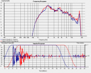
In your post #5126 you said the following;
“OS 12" with and without foam plug (Bulpren S28190). It seems foam attenuates uniformly.”
And you gave two wavelet graphs, one showing the response without foam and the other with foam.
I’m not 100% sure what you meant by “attenuates uniformly”, but I assumed you meant that the attenuation in SPL due to the addition of the foam plug at 18KHz (relative to say 2KHz) was the same as without the foam plug. Please correct me if my understanding is incorrect.
This seemed strange to me since it is in contradiction with the data that Dr. Geddes has published in the past.
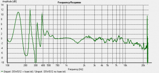
Since I’m not an avid supporter of wavelet graphs showing this type of data, I decided to import the files (from Jmmlc’s post #5132) into HOLMImpulse software as shown below. In order to see the difference between these two responses, I divided the “with foam” response by the “without foam”, also shown below. In this graph, it seems very clear to me that the response is about 4dB down at 18KHz compared to the level at 700Hz.
For the response variations below 700Hz, I would imagine that they are probably due to noise, and the smaller ripples in the response above this frequency may be due to diffraction. Regardless of this, I think the results show the trend of attenuation versus frequency much more clearly than the wavelet graphs you posted.
One more thing of interest was that the start of the impulse for the “no foam” response is 2mS longer than that for the “with foam” response, and the level of the “with foam” response is higher than “without foam” over the frequency range of 700Hz to about 1.3KHz. This suggests that the distance between the microphone and waveguide was not the same for the two responses. For the responses shown in the graph below, I set them to the same level at 700Hz. IMO, attention to discrepancies like this can only add credence to the accuracy of the results.
Regards
Peter
In your post #5126 you said the following;
“OS 12" with and without foam plug (Bulpren S28190). It seems foam attenuates uniformly.”
And you gave two wavelet graphs, one showing the response without foam and the other with foam.
I’m not 100% sure what you meant by “attenuates uniformly”, but I assumed you meant that the attenuation in SPL due to the addition of the foam plug at 18KHz (relative to say 2KHz) was the same as without the foam plug. Please correct me if my understanding is incorrect.
This seemed strange to me since it is in contradiction with the data that Dr. Geddes has published in the past.
Since I’m not an avid supporter of wavelet graphs showing this type of data, I decided to import the files (from Jmmlc’s post #5132) into HOLMImpulse software as shown below. In order to see the difference between these two responses, I divided the “with foam” response by the “without foam”, also shown below. In this graph, it seems very clear to me that the response is about 4dB down at 18KHz compared to the level at 700Hz.
For the response variations below 700Hz, I would imagine that they are probably due to noise, and the smaller ripples in the response above this frequency may be due to diffraction. Regardless of this, I think the results show the trend of attenuation versus frequency much more clearly than the wavelet graphs you posted.
One more thing of interest was that the start of the impulse for the “no foam” response is 2mS longer than that for the “with foam” response, and the level of the “with foam” response is higher than “without foam” over the frequency range of 700Hz to about 1.3KHz. This suggests that the distance between the microphone and waveguide was not the same for the two responses. For the responses shown in the graph below, I set them to the same level at 700Hz. IMO, attention to discrepancies like this can only add credence to the accuracy of the results.
Regards
Peter
Attachments
- Home
- Loudspeakers
- Multi-Way
- Geddes on Waveguides