Have you looked at the off-axis plots posted a page back?
Yes.
Yes.
It seems to me as a dip when compared with the off axis response. From the sims, it seems the way the lip is cut back effects the response. I guess you have a different observation perhaps?I didn't make the statement for semantics.. One perspective describes only a problem - without an explanation. My perspective *perhaps* suggests the reason for that problem.
It seems to me as a dip when compared with the off axis response. From the sims, it seems the way the lip is cut back effects the response. I guess you have a different observation perhaps?
No.. same observation.
To me though it appears that the changes result in extending the gain of the device both lower AND higher in freq. - effectively widening it's bandwidth. (..i.e. a wider bandwidth transmission line, or one that has a broad "q".)
Looking back at the geometry of test article over here:
http://www.diyaudio.com/forums/multi-way/103872-geddes-waveguides-423.html#post2162280
I further did some more measurements from 1M gradually going into about 8cm from the diaphragm.
Also referring to the SPL on and off axis plots shown here:
http://www.diyaudio.com/forums/multi-way/103872-geddes-waveguides-423.html#post2162214
It seems that the way the WG lip rolls back plays a major role in determining whether there will be an on-axis dip in the response or not. The next logical step would be to put the WG in a baffle to see whether this judgement is correct or not.
http://www.diyaudio.com/forums/multi-way/103872-geddes-waveguides-423.html#post2162280
I further did some more measurements from 1M gradually going into about 8cm from the diaphragm.
An externally hosted image should be here but it was not working when we last tested it.
Also referring to the SPL on and off axis plots shown here:
http://www.diyaudio.com/forums/multi-way/103872-geddes-waveguides-423.html#post2162214
It seems that the way the WG lip rolls back plays a major role in determining whether there will be an on-axis dip in the response or not. The next logical step would be to put the WG in a baffle to see whether this judgement is correct or not.
It seems that the way the WG lip rolls back plays a major role in determining whether there will be an on-axis dip in the response or not.
No surprises there.
The on-axis dip did not seem as significant with the other WGs posted. Overview below:
Jean Michel put lots of emphasis on the lip rollback, so I'd be interested in seeing how critical it can be and how compact this can be made.
An externally hosted image should be here but it was not working when we last tested it.
Jean Michel put lots of emphasis on the lip rollback, so I'd be interested in seeing how critical it can be and how compact this can be made.
Jean Michel put lots of emphasis on the lip rollback, so I'd be interested in seeing how critical it can be and how compact this can be made.[/COLOR]
Its really quite simple - the larger the radius, the less the diffraction and the less there is a hole. The "rollback", beyond a flat baffle, is of no significance whatsoever. A large radius to a flat baffle is "as good as it gets".
..The "rollback", beyond a flat baffle, is of no significance whatsoever. A large radius to a flat baffle is "as good as it gets".
The mouth resonance "trails" to each side of its dominate freq. (..i.e. higher in freq. and lower in freq.).
Increased spl "support" from an "infinite" baffle elevates the spl of the resonance and exaggerates the appearance of a "hole".
Ahh, now we have different opinions. If we look at post #4244, the WG has no baffle support, however, the "hole" seems to occur outside the WG where there is not support from the WG or baffle. My next step would be to add a 40cm diameter round baffle to that WG and see what happens. My guess would be the hole would be less significant, and closer to the infinite baffle simulation.
If we look at post #4244, the WG has no baffle support, however, the "hole" seems to occur outside the WG where there is not support from the WG or baffle.
Yes, as I mentioned before - I don't think it's a "hole". It's just that range of freq.s specific to the 0 degree axis that isn't "supported" by the waveguide. (..or isn't *as* supported by the waveguide.)
Ahh, now we have different opinions.
Wow - that almost never occurs in audio!
I've been slowly working my way through this thread 
Can a waveguide be made where the conical contour is square? This would be easy to construct from flat stock using a frame of quarter rounds for the mouth termination. Could the throat successfully transition from round to square?
I'd also like to know the name of the branch of math being used in the waveguide calculations as I'd like to go and get a handle on it. I'm hoping to hear something more specific than 'trigonometry'
It is the throat that is a problem, because a round to square transition is going to generate a lot of non-planar wavefront - HOM.
Waveguides use the full power of the "Wave Equation" / "Helmholtz Equation". Because of this the geometry that is used is not at all conventional and in fact even "trigonometry" does not suffice. The coordinates that have to be used are called "Seperable" and there are only a few that work: Spherical. Oblate and Prolate Spheriodal amd Ellipsoidal. Waveguides, to be exact, must fit one of those coordinate systems. By far and awy the most effective is the Oblate Spheriodal or OS, which is what I use in all of my designs, although I have uase Prolate Spheriodal on rare occasions.
The OS equations are not that complex:
y(x) = sqrt( yo^2 + x^2 Tan(theta)^2)
for the contour of an axisymmetric waveguide where theta is the design angle and y0 the throat radius.
How close does one have to hold to this? That's always a matter of debate, but I hold very close and I can see in the data and the sound when its not.
I think thats "more specific than 'trigonometry'"
Member
Joined 2003
Earl,
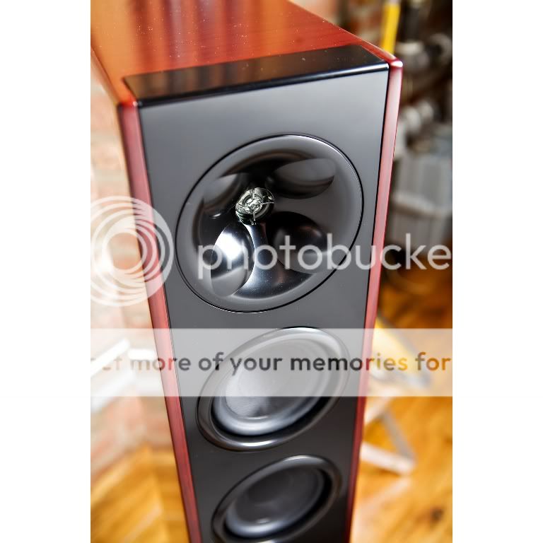
Any comment on the technical merits of the "bumps" in this WG?
I don't see any reason for them - not that logic or scientific rational has anything to do with audio.
What does the manufacturer claim, or is it asking too much for an explaination?
Yea, H.F. Olson came to mind when I saw them as well.
Member
Joined 2003
According to a magazine review, Klipch says: "the wider the horn becomes, the more inconsistent it becomes, especially at extreme high and low frequencies. A conventional horn with a large mouth and shallow depth will cause sound waves to lose contact with the horn walls which can result in less uniform dispersion...by adding bumps to the horn, the XT design slows the flare of sound waves and forces them to hug the horns walls, leading to better dispersion across the frequency spectrum."
I don't see any reason for them - not that logic or scientific rational has anything to do with audio.
What does the manufacturer claim, or is it asking too much for an explaination?
Yea, H.F. Olson came to mind when I saw them as well.
Before criticizing the idea out of hand, why not look at the patent that was assigned to Klipsch (last year, I believe). You can then get an idea about the problem, solution and application.
Regarding the text from a advertisement, I would not rely on that for information.
- Home
- Loudspeakers
- Multi-Way
- Geddes on Waveguides

