If the pressure response is independent of direction, i.e. CD and the axial response is independent of frequency, then the velocity of the source must be independent frequency, just as the power response is. How is this possible? No source can have a velocity that is independent of frequency (unless its EQ'd of course). Did physics somehow change and nobody told me? Oh its the new Mige0 physics! Now I understand.
No matter how gradual the trnsition from waveguide to baffle there will be a diffraction at this edge.
Though not as plain wrong as the mantra before, this one is IMO as misleading as the before statement.
It implies that the diffraction at the so called "mouth" of a horn is any different in impact than elsewhere.
Actually it does not matter *where* the contour does its bending - in the sense that you have to bend it towards 2Pi or 4 PI anyway – and, besides that its effects are of course stronger the higher the SPL at those points in space are of course.
This said - the exception is, if the contour does *not* bend somewhere – a conical part this is.
This IMO inherently leads to stronger "signal mirroring" and hence more pronounced wiggles due to comb filtering at specific points in space – best to be seen in sound field plots like here for example:
http://www.diyaudio.com/forums/multi-way/103872-geddes-waveguides-84.html#post2145108
or here:
http://www.gedlee.com/images/Abbey_map.jpg
Besides that - *if* the contour would be made asymptotic towards an infinite baffle for example – the *effects* of that "mouth" diffraction would be spread out over a very wide area – and anybody would have a really hard time to detect a discrete "standing wave" over the so called "horn mouth".
Michael
Last edited:
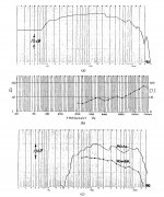
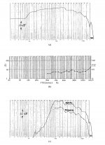
– who's to explain where *exactly* those CD behaviour can be found in the (new) SUMMA polar plot below ?
One can non-arguable say that the directivity is constant below 250Hz or about there exactly

Maybe true for most 2-ways. But this is different, it is made in Finland! It's a diy kit from the early 90's. Not much info on the net apparently. Try searching Hifi 12/C.
It's a diy kit from the early 90's. Not much info on the net apparently. Try searching Hifi 12/C.Well, then most 2-way speakers are poorly executed designs. What make and model is the speaker you showed?
Maybe true for most 2-ways. But this is different, it is made in Finland!
Did you measure it yourself? Would you be so kind to post data that is less smoothed (1/6)?
Did you measure it yourself? Would you be so kind to post data that is less smoothed (1/6)?
I think that the "wavelet smoothing" is also an issue since this is not standard and we have no way to compare what is called "1/3 octave wavelet" smoothing to the more standard methods used everywhere else. While I would certainly encourage the use the wavelets as a better approach than say CSD, and possibly data smoothing, it must be understood that comparing anything done with them to other methods is not going to be possible.
Michael,Nothing gets "more true or the *one* truth" on earth by simply preaching / repeating any of these silly mantras. ("IF the axial response does not fall then the device cannot be CD, its that simple." - that is)
I am not so sure about that. Everytime I try to turn some tweeters into (sort of) CD devices by putting them back to back in dipole fashion, the response in the (sort of) CD region has a tendency to fall - compared to the single naked tweeter.
Below are simulations, but I could veryfy the sims for the Dayton with my own measurements.
Attachments
Hi,
Maybe it's because of the first dipole notch that's causing falling response. In theory one get's multible notches in dipole, but in practise the notch deepness may not be very big and seems like response variations.
- Elias
Maybe it's because of the first dipole notch that's causing falling response. In theory one get's multible notches in dipole, but in practise the notch deepness may not be very big and seems like response variations.
- Elias
I am not so sure about that. Everytime I try to turn some tweeters into (sort of) CD devices by putting them back to back in dipole fashion, the response in the (sort of) CD region has a tendency to fall - compared to the single naked tweeter.
Did you measure it yourself? Would you be so kind to post data that is less smoothed (1/6)?
Yes I measured the data. If 1/6-octave wavelet is fine I can post that
The speaker is measured in a living room. Outdoor not possible before the snow melts
Important thing what everyone may not understand is that there is a limit how narrow bandwidth one can have without having the data poisoned with room reflections. It comes from the Heisenberg's limit.
- Elias
I think that the "wavelet smoothing" is also an issue since this is not standard and we have no way to compare what is called "1/3 octave wavelet" smoothing to the more standard methods used everywhere else. While I would certainly encourage the use the wavelets as a better approach than say CSD, and possibly data smoothing, it must be understood that comparing anything done with them to other methods is not going to be possible.
That's why I asked for more data that might look more "familiar". I doubt that Elias' diagrams show the whole truth.
Yes I measured the data. If 1/6-octave wavelet is fine I can post that
The speaker is measured in a living room. Outdoor not possible before the snow melts
Important thing what everyone may not understand is that there is a limit how narrow bandwidth one can have without having the data poisoned with room reflections. It comes from the Heisenberg's limit.
- Elias
So the smoothing comes from a lack of data points? Either way it's a sugar coated diagram. Not really useful.
Nothing gets "more true or the *one* truth" on earth by simply preaching / repeating any of these silly mantras.
Or just saying it's wrong with nothing to back that postion up. The key to this is it follows the devices power response, whatever that is. With a compression driver it's real predictable what the outcome is. That's why I asked you where your compression driver and horn measurements were but of course you don't have any that support your position. Here is more support for one of those silly mantras and anyone with any real world experience using CD horns and compression drivers will tell you it absolutely the "one truth"
Here's a few quotes
Previous horns were judged on their ability to generate flat response on axis with typical compression drivers. This persisted, even though compression drivers were known to fall off in power response above the midband. A typical driver whose power response rolls off at 6dB per octave above 3 kHz (Newman [3] with a reciprocal increase in directivity index. The compression driver would then be acoustically equalized, but only on axis, as shown in Fig. 5.
When this compression driver is loaded by a constant directivity horn, the axial response follows the power response of the driver, as shown by Fig. 6. The very high midband efficiency given by horn loading allows equalization for both flat axial and, at the same time flat power response.
The source
Improvements in Monitor Loudspeaker Systems - Lansing Heritage Forums
Rob
Attachments
One more time and maybe I can make this a littlke clearer so that everyone can follow it.
Power(f) = R * V(f)^2, where R is the radiation impedance (real part) and V(f) is the frequency dependent source velocity. This is a fundamental law of physics and is not open to argument.
Now Power(f) is also the integral of Pres(f) ^2 over a surface enclosing the source (think of just summing all the points on a sphere), where Pres(f) is the pressure response, another fundamental relationship in physics that is beyond question.
Now back to the first equation. R is the radiation impedance and it is also well know that this term always becomes flat - independent of frequency - at higher frequencies, -this is true of any source with a waveguide, horn or not. Lets assume that we have CD, then Pres(f) is not dependent on directivity and the Power(f) will go as the square of Pres(f). Now if further, Pres(f) is flat (independent of f) on axis (or any axis since it is CD), then it's simple to see that the Power(f) will be independent of f and the pressure is independent of direction. This is what makes CD desirable.
This all means that if the Power(f) is independent of frequency then the velocity of the source must also be independent of frequency. But no source acts like this, all sources are resonant devices and above resonance the velocity must fall at -6 dB/oct (for a constant source voltage). This means that if the device is CD and uses any normal non-EQ'd source that the Power(f) must fall at -12 dB/oct above resonance and at higher frequencies. This equates to a pressure response that falls at -6 dB/oct for any real source which exhibits constant directivity.
A piston source has a changing directivity and it just so happens that its directivity narrows at precisely the same rate that the power falls. This yields a pressure response on axis that is independent of frequency, but the source is, of course, not CD and its power response falls with frequency.
The extent to which any source is CD can be seen quite simply by looking at the HF falloff. If it is less than -6 dB then it must be getting narrower at HF - 0dB (i.e. flat) and its directivity must be narrowing as a piston (narrowest) and if it is -6 dB then its directivity is not changing, i.e. CD. All real sources will lie somewhere between these two extremes.
This is all simple math and if your results do not agree with these then they are incorrect and you should try and figure out what you did wrong.
Last edited:
So the smoothing comes from a lack of data points? Either way it's a sugar coated diagram. Not really useful.
No. There is 400 data points logarithmically per decade, for 3 decades that's 1200 datapoints. Well enough.
Think it from this point: Let's say there is a time window of 4ms between the direct sound and the first room reflection. During the 4ms you need to determine the amplitude and bandwidth of a signal at the frequency of interest. If you extend your study beyond 4ms your data is garbaged by reflections.
Old fashioned people usually sum all (or most) of the room reflections in FFT and then try to 'smooth' the response in the frequency domain to look good and pretend they are having it correctly.
- Elias
So the smoothing comes from a lack of data points? Either way it's a sugar coated diagram. Not really useful.
MArkus, it means that the data is in room with reflections which of course is smoothing of the directivity response as well. Its a totally pointless comparison.
MArkus, it means that the data is in room with reflections which of course is smoothing of the directivity response as well. Its a totally pointless comparison.
Why would anyone post such diagrams? Only anechoic data would make any sense.
Here's an example of the measurement conditions. First room reflections comes at 4ms.
At the freq response graph I posted earlier, there is no reflection contaminations in the data above 500Hz, due to the selection of the wavelet therein, and thus a comparison can be made.
- Elias
An externally hosted image should be here but it was not working when we last tested it.
At the freq response graph I posted earlier, there is no reflection contaminations in the data above 500Hz, due to the selection of the wavelet therein, and thus a comparison can be made.
- Elias
- Home
- Loudspeakers
- Multi-Way
- Geddes on Waveguides