Hi,
It is more correctly, people who have both DACs to give a review")
Power requirement for AK4396 board is 5.2V/0.2A and for PCM5102 board is 7.5 to 9.0V/0.2A.
For XMOS board there may be 2 separate power supplies: first is for USB part 5.0V/0.4A, and another one for oscillators and reclock 5.0V/0.2A.
Regards,
Joro
what are the differences in sound signature between the PCM and the AKM dac boards?
What is the power supply requirements for the dac boards?
There is option for 3 separate power supplies on the xmos board? What are the Voltage and ampere requirements ?
It is more correctly, people who have both DACs to give a review
Power requirement for AK4396 board is 5.2V/0.2A and for PCM5102 board is 7.5 to 9.0V/0.2A.
For XMOS board there may be 2 separate power supplies: first is for USB part 5.0V/0.4A, and another one for oscillators and reclock 5.0V/0.2A.
Regards,
Joro
I have both, but I couldn't manage to have a decent earing.
I'll start with the PCM, I'd implement its combo like this:
EDIT: scrolled the manual, and found:
Well, can't be more clear than this. Thank again!
I'll start with the PCM, I'd implement its combo like this:
Joro, the "USB part" will be still supplied by USB, right?2. External power supply for the PCM5102 board – +7.5V to +9V on pin 12. This power supply is feeding PCM5102 and generators and reclocks on I2SoverUSB board. On I2SoverUSB board, USB jumper is installed and on PCM5102 board, configuration jumpers are opened.
EDIT: scrolled the manual
, and found:Second variant:
On I2SoverUSB board USB jumper is opened; and on PCM5102 board configuration jumpers are opened. First power supply is feeding the USB part and the second power supply is feeding generators, reclocks and the PCM5102.
An externally hosted image should be here but it was not working when we last tested it.
Well, can't be more clear than this. Thank again!
Last edited:
Hi,
Yes, with 5V battery, there won't be a problem. When the battery is fully charged, the voltage mustn't be higher than 5.5V.
Yes, you could connect the battery directly if the above condition is met.
The best way depends from what will be pleasant for you (according to your system) and with some tests done, I recommend at least one external PS (or battery) for the oscillators, reclock and the DAC.
No problems with 384kHz and DSD 128!
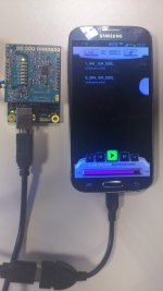
Some good news for Android users.
I've tested the device with Samsung Galaxy S4, HTC One X by using this program,
https://play.google.com/store/apps/d...audioplayerpro
I've tested it up to 384kHz and works perfect. Of course with external power supply for the USB part. If one can install this program (there is a trial) and have USB OTG, XMOS board must be working. If someone test his Android device, please share.
Regards,
Joro
What about power up both AK4396 and Xmos with 5V battery? Could I connect battery directly? Which is the best way?
Problems with 384 sampling rate and DSD128?
Yes, with 5V battery, there won't be a problem. When the battery is fully charged, the voltage mustn't be higher than 5.5V.
Yes, you could connect the battery directly if the above condition is met.
The best way depends from what will be pleasant for you (according to your system)
and with some tests done, I recommend at least one external PS (or battery) for the oscillators, reclock and the DAC. No problems with 384kHz and DSD 128!
Some good news for Android users.
I've tested the device with Samsung Galaxy S4, HTC One X by using this program,
https://play.google.com/store/apps/d...audioplayerpro
I've tested it up to 384kHz and works perfect. Of course with external power supply for the USB part. If one can install this program (there is a trial) and have USB OTG, XMOS board must be working. If someone test his Android device, please share.
Regards,
Joro
Attachments
Hi Joro,
I was reading the Xmos manual and then the AK4396 manual and I just want to double check with you on external power.
If using just Xmos board you can use 2 regulated PSUs, one for the board Pin 1-2 and remove USB jumper and another one for reclock Pin 11 and 12.
If using your AK4396 board, you can still only use 2 regulated PSUs, remove USB jumper on Xmos and power Pin 11-12 on AK4396 (equivalent to Pin 1-2 on Xmos?) and remove configuration jumper on AK4396 and power on Pin 9-10, correct? No need to supply Pin 1-2 with external regulated PSU on Xmos?
Thanks
Do
Hi,
Do, you've got it perfect
Regards,
Joro
...
If using just Xmos board you can use 2 regulated PSUs, one for the board Pin 1-2 and remove USB jumper and another one for reclock Pin 11 and 12.
If using your AK4396 board, you can still only use 2 regulated PSUs, remove USB jumper on Xmos and power Pin 11-12 on AK4396 (equivalent to Pin 1-2 on Xmos?) and remove configuration jumper on AK4396 and power on Pin 9-10, correct? No need to supply Pin 1-2 with external regulated PSU on Xmos?
Do, you've got it perfect
Regards,
Joro
Hi,
You just have to sign in the spreadsheet, from my signature
Regards,
Joro
I am interested in joining group buy for 1 x XMOS board, please advice. thank you.
You just have to sign in the spreadsheet, from my signature
Regards,
Joro
Hi Joro,
Am VERY interested with your USBtoI2S and DAC solution. I have one big question though before I start signing up :
Is it possible to have an option where the components for the analog stages are NOT soldered in, and instead i have pins or something similar that I can use to access the differential output (and VCOM) of the DAC chip? From what I see in the product gallery, output is converted to single ended already..
To any interested in adding the JG Filter buffer : I don't think that it will add anything to this setup. The LME49710 chip and its supporting parts already implement a low pass filter (and buffer ??), methinks.
Thanks MisterRogers for that feedback ... Part of the reason why I was asking for a "clean" analogue stage was so that I could apply Joachim's LPF without interacting negatively with existing LPFs. Glad to know that the filter buffer's effects extend to this DAC as well.
P.S. Checked back on the filter buffer thread, the low pass implemented has a corner frequency at 100Khz. The default LPF described in the AKM4396 datasheet has it at 125Khz. Maybe that's why the effects are still audible.
P.S. Checked back on the filter buffer thread, the low pass implemented has a corner frequency at 100Khz. The default LPF described in the AKM4396 datasheet has it at 125Khz. Maybe that's why the effects are still audible.
Hi,
Probably, the program for soldering has to be changed. I can ask the guys, who do that. There is no problem to unsolder the unnecessary components. I can tell you which ones
Regards,
Joro
...
Is it possible to have an option where the components for the analog stages are NOT soldered in, and instead i have pins or something similar that I can use to access the differential output (and VCOM) of the DAC chip? ...
Probably, the program for soldering has to be changed. I can ask the guys, who do that. There is no problem to unsolder the unnecessary components. I can tell you which ones
Regards,
Joro
The range seems to be:
for AK4396 board : 4.8v to 5.4v
for "main board" : 3.9v to 5v
Only 2 dc power supplies are needed. Supplying the AK4396 board with power already supplies the reclockers / generators in the main board.
Source is AK4396_board.pdf, based on schematic diagram for recommended minimum for power supplies.
for AK4396 board : 4.8v to 5.4v
for "main board" : 3.9v to 5v
Only 2 dc power supplies are needed. Supplying the AK4396 board with power already supplies the reclockers / generators in the main board.
Source is AK4396_board.pdf, based on schematic diagram for recommended minimum for power supplies.
Hi joro
I want to have 3 separate dc power supplies for the xmos and the AK4396 board.
You have specified two 5V dc for the xmos board and one 5.2 V dc for the Ak board
What is the tolerance level for the dc V ? Between 4.5 to 5.5 V ?????
thanks
kp93300
Last edited:
Hello, just to be sure: using a XMOS + PCM5102 combination i can power both boards using a single 5V linear PSU connected to PIN 1 & 2 on PCM5102 PCB, correct (first variant in site's PCM5102 pdf power section)? Should i solder PSU's wires to the pins solder cone on the upper surface of the PCB?
Would this solution give better results than powering PCM5102 PCB using 7.5V linear PSU and XMOS using direct USB interface 5V power?
Would this solution give better results than powering PCM5102 PCB using 7.5V linear PSU and XMOS using direct USB interface 5V power?
- Status
- This old topic is closed. If you want to reopen this topic, contact a moderator using the "Report Post" button.
- Home
- Group Buys
- GB thread for XMOS DSD 384 kHz / 32bit USB