Hi elwood,
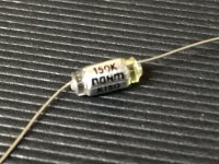
That is a polystyrene capacitor. One of the best kind of capacitors you can get. These are very heat sensitive and easily short if the lead gets hot enough. Leave some room between the body and solder point. If you can put a clamp or heat sink on the lead between the body and solder joint - do it. It can help to tin the lead and also the pad first, then install the capacitor, soldering the tinned pad and lead quickly.
I use these a lot and developed a rhythm for soldering them quickly. I had to ruin a few before I figured out how hot I could get them. Interestingly, the lower powered or low temperature irons were the worst for overheating these capacitors. With practice you won't need the heat sink on the lead anymore.
-Chris
Hi Erlend,
That's true, but there is no real replacement for those fine components. I thought they weren't made any more because there isn't anyone making the film used.
I was very unhappy that they were discontinued. Maybe someone in China will take up production. One can only hope.
-Chris
That's true, but there is no real replacement for those fine components. I thought they weren't made any more because there isn't anyone making the film used.
I was very unhappy that they were discontinued. Maybe someone in China will take up production. One can only hope.
-Chris
A new thread for an updated board group buy has been started.
https://www.diyaudio.com/forums/group-buys/354704-gb-buy-salas-ultrafsp-riaa.html#post6209956
https://www.diyaudio.com/forums/group-buys/354704-gb-buy-salas-ultrafsp-riaa.html#post6209956
I'm buying parts for this now, and looking at a transformer.....
Hammond 185C36, 43 VA as 18-0-18.
I also have a monster 216 VA as 18-0-18 that I am not using, already mounted in a box, with connectors on the secondary side built.... I guess that is total overkill, but is there a good reason not to use this monster transformer?
Thanks!
.
Hammond 185C36, 43 VA as 18-0-18.
I also have a monster 216 VA as 18-0-18 that I am not using, already mounted in a box, with connectors on the secondary side built.... I guess that is total overkill, but is there a good reason not to use this monster transformer?
Thanks!
.
I'm buying parts for this now, and looking at a transformer.....
Hammond 185C36, 43 VA as 18-0-18.
I also have a monster 216 VA as 18-0-18 that I am not using, already mounted in a box, with connectors on the secondary side built.... I guess that is total overkill, but is there a good reason not to use this monster transformer?
Thanks!
.
I used the dual bobbin hammonds, initially and they often hummed under any load. I always subbed in Antek transformers without issue. I don't know anything about this particular variety. I can recommend Antek.
As long as the larger transformer is away from the signal boards, I think you would be ok. I have mine a few feet away with the RAW supply and an umbilical cord.
Thanks. This monster is some sort of chinese cheapie ( $25 CDN ) . It shakes. I'll find something else.
Also, I'm a bit confused re: resistors in the package.
The resistor marked R3X is 6.2K. So, R6x should be 33 Ohm, which is included.
But also included was a 9.1K and 27.5 Ohm.
Is this a choice I need to make based on the 2sk117? Or is the marking R3X highlighting which pair I should use?
Also, I'm a bit confused re: resistors in the package.
The resistor marked R3X is 6.2K. So, R6x should be 33 Ohm, which is included.
But also included was a 9.1K and 27.5 Ohm.
Is this a choice I need to make based on the 2sk117? Or is the marking R3X highlighting which pair I should use?
Use 30-32 VAC per Raw DC channel for UFSP. Not 36VAC. There are 32+32 single transformers (four wire secondaries). Providing secondaries electrical isolation when building with one transformer.
There are also 15+15 VAC transformers to wire each unit in series for 30V when building with two Tx fully double mono.
There are also 15+15 VAC transformers to wire each unit in series for 30V when building with two Tx fully double mono.
Hi Salas,
Nice to hear from you, Happy New Year!
I am building V1 of the Folded Simplistic Phono section, which I thought was 2 transformers,each being 18-0-18. Should that be scaled back to 2x 15-0-15?
Happy new year!
You may use 15-0-15 if with 1R 2W Rd/Link resistors in the raw board. 18-0-18 need 27R 3-5W.
Is there a schematic anywhere to look over? How about any S/N specs/
Hi
This blue FSP version is no more, but there is its successor in black, the UFSP.
UFSP schematics
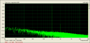
Its a no global feedback two gain stages plus buffer design of about 62dB max gain (HMC MM MC LMC sensitivity DIP switch selectable) and about 0.02% THD mainly 2nd harmonic at nominal output. Which is -10dBV consumer level (316mV at 5cm/sec record velocity) with ~40 Ohm output impedance.
A typical non averaged FFT chart at max sensitivity setting when driven with 1kHz 0.25mV shall compare to this one from the prototype:
Attachments
The Blue one is on my workbench right now.
I measured the IDSS of 2 of the 2sk117 from the build kit I got a LONG time ago.
1) Strap Gate and Source together,
2) Connect 100 Ohm resistor from source+gate to ground
3) Meter set to measure voltage across 100 ohm resistor
4) Apply 10VDC to Drain
Jfet 1: Meter reads .35 V, I = V/R, so I = 0.0035 A or 3.5 mA.
Jfet 2: Meter reads .375 V, I = V/R, so I = 0.00375 A or 3.75 mA.
Instructions say use 6.2 R3x and 33 ohm R6x when IDSS near 5 ma.
So, that is what I am using.... I assume 3.5 is close enough to 5 ma ?
- Home
- Group Buys
- GB for Salas Folded Simplistic Phono PCB