Mr.Koran said : If you want a value, Please see from my boards
Me said : What's number of opamp which you covered with epoxy glue ?
Mr.Koran said : he he he ha ha ha
Me said : Do you want me paid you again ?
Mr.Koran said : No, I want you only use my boards not clone me again !
Me said : OK, I see. Do you want my Jadis Orchestra wiring layout ?
Mr.Koran said : Yes, Please
Me said : 10,000 USD NOW !!!, Thanks see you later - bye
Mr.Koran said : ?!?
Me though : he he he ha ha ha
You though : .............................
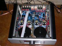
Let's see what's picture me received !!!
AHHH...I think him should stop his job and gone to work at GAMUT AUDIO !!!
Please compare his PCB with my post#7 it's can be instead of original !!!
No comment..................."Dangerous man for High-End Products"
AHHH...I think him should stop his job and gone to work at GAMUT AUDIO !!!
Please compare his PCB with my post#7 it's can be instead of original !!!
No comment..................."Dangerous man for High-End Products"
Attachments
New product of GAMUT !!!
I found new integrated amplifier of GAMUT we called "DI 150" please notice at all boards it used as same as GAMUT D200 MKIII but it used 100KA volume in the front of schematic (passive volume)
I think it only used UNBALANCED connector by shorted (-) input to ground and used only (+) and (G) for integrated amplifier
Thanks
analog guy
Attachments
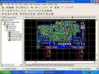
PROTEL !!!
He told me it's a protel99SE, I request its PCB files but I never got any answer !
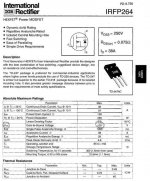
Latest answer is "I suggest you use BUZ901 instead of IRFP264 because it can bias VGS much more than 3.9V with idle current 150mA ,IRFP264 = 3.5V with idle current 65mA"
So waiting for me to clone it again
Thanks
analog guy
He told me it's a protel99SE, I request its PCB files but I never got any answer !
Latest answer is "I suggest you use BUZ901 instead of IRFP264 because it can bias VGS much more than 3.9V with idle current 150mA ,IRFP264 = 3.5V with idle current 65mA"
So waiting for me to clone it again
Thanks
analog guy
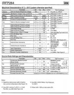
Nelson Pass said:Since the data sheets show 4 parallel MOSFET chips inside
these devices, how do we justify the notion that the amplifier
would have a single device output stage?
One wonders. Marketing ploy, I guess. Although it is conceivable that these are adjacent chips linked together on the same die, that would be essentially the same as a single device with larger surface area.
Are you sure they aren't using something akin to the MAG90X95 complementary lateral MOS'es in matched quads? That would kind of make sense.
ANALOG GUY: He told me it's a protel99SE, I request its PCB files but I never got any answer !
It is Protel 99SE indeed, but providing his files would be the same as giving away his (cloned) design

If you bump into a schematic, please share.
Problem about VGS ?
Could anyone tell me about VGS ?
I used 3.9V for BUZ901 it's work very well but when I used 3.9V for IRFP264 it's damage and made my boards burnt !!!
I think maximum VGS of IRFP264 = 4V isn't it ?
Does anyone know about maximum VGS of BUZ901 ?
I don't know well about VGS of quasi complementary mosfet circuit, when used low VGS with IRFP264 (3.4V) it's has little crossover distrotion same CLASS-B amplifier (measured with oscilloscope) why ?
I have no picture for my question ,sorry
Thanks
analog guy

Re: VGS 2 to 4V ?!?
The 2 - 4 V is the "threshold" region where the transistor
begins to conduct current. It varies quite a bit.
The Vgs max is 20V where the Gate actually breaks.
ANALOG GUY said:It has other VGS ?!?
Minimum VGS is 2V and maximum is 4V, What's this?
The 2 - 4 V is the "threshold" region where the transistor
begins to conduct current. It varies quite a bit.
The Vgs max is 20V where the Gate actually breaks.
Suggest me please
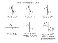
This's my picture and result from trimming IRFP264 VGS, I like VGS 3.4V with mini crossover distrotion from quasi complementary circuit but when I measured with oscilloscope I don't like its graph !
Then I trimming IRFP264 VGS to 3.66V its curve is very well on +/- sine junction but it was damage and burnt after I only run on 1 minute !!!
My question is "If I want to use VGS 4V or more with BUZ901, Could I trimming much more than 4V ?"
Best regard
analog guy
Attachments
First simulation !
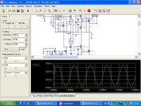
Now I successful with QUAD PARALLEL BUZ901, VGS only 2.985V
Input : 0.707 Vrms, Frequency 1Khz
Peak AC 8 Ohms : 46.79 Vrms
Peak AC 4 Ohms : 46.73 Vrms
Peak AC 2 Ohms : 45.51 Vrms
Peak watt 8 Ohms : 193.5 Wrms
Peak watt 4 Ohms : 384.8 Wrms
Peak watt 2 Ohms : 701.3 Wrms
Peak current 8 Ohms : 5.849 Amps
Peak current 4 Ohms : 11.68 Amps
Peak current 2 Ohms : 22.76 Amps
Clonning project is coming soon !!! he he he
Best regard
analog guy
Attachments

Re: Running the Gamut
I can't resist low-hanging fruit, and the Vgs question qualifies.
On the other hand, poking fun at Gamut is easy, but not polite.
TomWaits said:Here I am poking fun at GAMUT on another thread but I want to know what tweaks N.Pass's attention to this design?
I can't resist low-hanging fruit, and the Vgs question qualifies.
On the other hand, poking fun at Gamut is easy, but not polite.
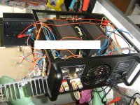
New project with 100% CLONED PCB
2SK389 jfet folded cascode with Signetics NE5534N half stage opamp (please see data sheet of NE5534N) maybe likely dual jfet opamp but it used real JFET !!! surprise !!!
Semi quasi complementary / phase bridged single mosfet 32A
Local feedback with less negative feedback and constant current input buffer
Attenuator input gain for several preamp and easy to use passive volume !
+/- 70V 8A power supply rails
22,000*4 Macon filter capacitor
0.75A idle current
80 degree thermal fuse
25A for 2 Ohms load current protection
Input/Output oscilation protection
Welcome to RE-ENGINEER world
analog guy
Attachments
- Home
- Amplifiers
- Solid State
- Gamut D200 clone !!!