rabbitz said:... and what I ended up doing was 25V into 4R. This keeps the temperature down and still allows 4R capabilities. This is for a stereo module only BTW.
You seem to imply heat is a problem but rather it's inherant in having a higher power capability. It seems you merely need a bigger heatsink if you want that output. While I have no argument that not everyone needs to try to squeeze 50W out of the chip, citing higher voltage as bad, when there is no thermal cutout observed, is a bit premature.
Hi,
using a supply voltage selected to suit the load impedance is crucial.
The datasheet design process confirms that lower impedances need lower voltages.
The datasheet also confirms that as power increases so does the need for a bigger sink. But there is a limit, the Rth c-s of the single chip. It becomes the bottleneck. This effect is worse with lower impedances.
One cannot maintain supply voltage as the load impedance drops by using ever larger heatsinks.
! said:
You seem to imply heat is a problem but rather it's inherant in having a higher power capability. It seems you merely need a bigger heatsink if you want that output. While I have no argument that not everyone needs to try to squeeze 50W out of the chip, citing higher voltage as bad, when there is no thermal cutout observed, is a bit premature.
I'm not saying higher voltages are bad as they work very well on the right load. I've just found it easier to tailor the rail voltage to suit the speaker and in my application could have some nasty impedance loads.
AndrewT has nailed it and I was passing on my experiences with the LM4780 configured in stereo. You can only throw so much heatsinking at the chip.
I have no idea how much of this applies to the chip in parallel and bridged mode as I've only used it in stereo.
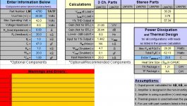
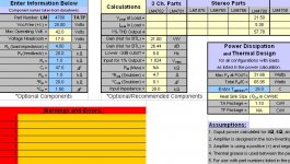
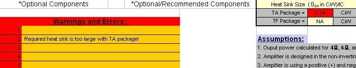
This is the recommended heatsink size for 34V + 4R according to the National Semi design guide and it's saying it's too big for the chip.
Attachments
On another level, the actual chip packageing has its own thermal bottleneck... the silicon chip inside can heat up at a faster rate than the case/sink junction can get the sink to respond... so at some point, everything will burn off even before the heat reaches the sink. At that point it does not matter what size heatsink you use...it will burn.
no.Nordic said:On another level, the actual chip packageing has its own thermal bottleneck... the silicon chip inside can heat up at a faster rate than the case/sink junction can get the sink to respond... so at some point, everything will burn off even before the heat reaches the sink. At that point it does not matter what size heatsink you use...it will burn.
Thermal inertia applies certainly, but so too does transient survivability.
AndrewT said:Hi,
using a supply voltage selected to suit the load impedance is crucial.
The datasheet design process confirms that lower impedances need lower voltages.
The datasheet also confirms that as power increases so does the need for a bigger sink. But there is a limit, the Rth c-s of the single chip. It becomes the bottleneck. This effect is worse with lower impedances.
One cannot maintain supply voltage as the load impedance drops by using ever larger heatsinks.
Certainly voltage increase can't be infinite. That is a higher threshold, different than looking at a graph that shows what happens when a heatsink interface or 'sink itself is insufficient to keep it cool enough. Remember even then, a datasheet is a guaranteed minimum, worst-case scenario.
I think it would be fairer to say that given a good enough heatsink, voltage above a certain point doesn't have a purpose, but there is still a range that could be used without expectation of problems, that use of an existing supply-components is weighed against the actual voltage and performance of the amp as related to the heat generated. Plus, we're playing music, not a sine wave, so it is possible to have momentary peaks that don't trip the Spike protection because the average heat is lower, momentary heatsinking effectiveness has a lot to do with the 'sink and die temp up to that moment.
We can also see this from some passages in the app notes like
there are two output power specification guarantees: 60W (min) into a 4Ω load using ±28V supplies and 50W(typ) into an 8Ω load from ±35V supplies. Using these two conditions and the theoretical
maximum power dissipation equation ...
... These results show that the IC can handle a maximum of
≈ 40W of continuous power dissipation without SPiKe Protection
being turned on under continuous sinusoidal input
with proper heat sinking.
... Your electrical design parameters and thermal management
may be different, changing the achievable results. As always,
lab testing is recommended to verify any solution.
[AN-1192, pg. 3,4]
I for one would as soon have an amp capable of higher momentary peaks to keep dynamics, even if it couldn't play a sine wave at that level indefinitely, but I don't mean to suggest completely abandoning voltage considerations, just that there is a little latitude.
Hi Guys,
I built a pair of the 3886 chip amp modules from Chipamp.com, each with its own power supply. (the dual mono setup) I usd no volume pots or anything like that. I use a Harmon Kardon receiver for a preamp which feeds the Chipamp directly.
Initially, I had a bunch of 12VAC transformers on the shelf so I used two of those for the power supply. You can see these in the photos on my blog. That gave me a fairly low B+ but it worked well. I did all of my initial testing on a pair of really nice speakers that were built by a DIYer named Keith Kidder. More details at my blog.
A couple weeks after I finished my Chipamp, I finally received a pair of toroid trannys with dual 22V secondaries which I swapped in. My contribution to this thread is that my first observation besides the reduction of mechanical noise with the toroids was that the bass response with the higher voltage toroids seemed to be more sterile. Sure, the amp is obviously more powerful and the bass is adequate, but with the 12V supply trannys, the bass was really rich and seemed to resonate in the room at down near 25Hz. The comments that you guys are making regarding voltage and response seem to imply that maybe my observation is warranted. I'm still digesting all that is being posted in this thread to try to figure it out.
http://gdsamps.wordpress.com/chip-amp-in-nabu-chassis-60-wpc/
Graydon said:a pair of toroid trannys
Any conclusions drawn out of multi-variable experiments are pretty meaningless. Yes, it's possible that the chips play better at lower voltage. It is also possible that you prefer the sound of EI transformers.
Ime PS transformers sound surprisingly different and i really wish i knew what makes some sound better.
Leolabs said:Guys,did zdr mention his source and output level,yet?????
Nope, but here it is
")
The sources are the same for both setups - Original CD2008 and PC lossless->DAC Diyeden SVDAC01 Plus with modified output (OPA627 and no nasty caps in series).
I still did not get the chance to test it without 4X10000uF in PS. I did a test with caps on the input (Audyn CAP 4,7uF, 400V) and did not make much difference (if any at all). DC was zero across the caps so out they went again.
I did make another set of speakers though - HATT MKII, completely different animal, and will be doing some A-B comparisons soon. Vincent also developed a problem in preamp's right channel so I had to fix that too (bad solder joint under a tube).
All those are the reasons I was quiet for a while. I will be doing some tests soon and will play it again to my wife - she can hear much more differences.
zdr
I have some proac clones too, which I'm running with mauro's rev C (twisted pear audio kits). Running it of a preamp (pga2310) they do sound fine to me ! Though that's something completely different from a gainclone.
You're welcome to come by to compare, only 30 minutes away from you in Leuven (except for traffic)
A8
Thanks for the offer, I might accept it since nothing that was suggested made a difference. Don't get me wrong, it sounds ok until I compare it to Vincent SV-236. I tried now without 10000uF caps and with quality caps on the input - no difference. I even tried with completely different speakers (HATT MkIII) and still it's a mediocre, ~300 eur sound. My expectations were somewhere in 2000K area. I maybe expected too much?
You're wellcome, pm me to see when it fits.
Do you have a way to measure the gainclones freq response ?
I have heard gainclones on electrostats, no problem though they were certainly running hot ! Apogees are not very sensitive speakers and definitely not an easy load so...
Another option is to turn it in bridge mode to make a subwoofer amp ;-) That'll surely beat a 300 euro sub amp !
A8
zdr said:My expectations were somewhere in 2000K area. I maybe expected too much?
The LM4780 is good but not at that sort of level IMO. You have to get into AKSA territory to achieve that. I have an AKSA 55N+ as a reference and no other amp has come close.
zdr said:Thanks for the offer, I might accept it since nothing that was suggested made a difference. Don't get me wrong, it sounds ok until I compare it to Vincent SV-236. I tried now without 10000uF caps and with quality caps on the input - no difference. I even tried with completely different speakers (HATT MkIII) and still it's a mediocre, ~300 eur sound. My expectations were somewhere in 2000K area. I maybe expected too much?
Additional PS filter capacitor improves the supply voltage. Hence, IMO, it should not be expected that removing 10000uf cap will imprve anything. However, downside is possible.
What really disappoints you? Isn't it faithful reproduction of input signal? Hearing test is really very subjective.
The problem with this user-preception-as-evaluation is we don't have a baseline.
You compare it to another amp but personally, I've never heard that amp and don't know it's particular benefits. Further what is missing is a thorough description of exactly what sound you are looking for.
Some consider accurate response, a faithful gain on the input signal to be "boring" or bland, whatever the term du jour. "Maybe" you do too, but if what you are seeking is not a mere gain on a flat response, you will have to specifically tailor the amp to your goal. Maybe a gainclone can accomplish that or maybe it can't, it depends on what the goal IS.
I will say one thing though, unless your goal is distortion (which is not necessarily a bad thing, it depends on who you ask and context), there is no justifiable reason not to use more than 1000-2200 uF capacitance. Beware of advice by those only considering a handfull of chipamp kits because they are not considering the grand scheme of chipamp power circuitry, they are only considering some crude or simple implementation as if you had no alternative at all but to have either a few giant caps or only a local resevoir that is very large.
Ignoring the possibility that you may want to color the sound for a moment, it is wrong to build a chipamp with only one 1000 cap or distant much larger caps on the PSU rails. People perpetuate that myth by misunderstanding the datasheet, that when a datasheet shows 1000uF it does NOT AT ALL MEAN the only thing in the circuit past a bridge rectifier is this lone cap per rail. What it means is, you are supposed to assume ideal and perfect power in your device right up until this point in the circuit, including a hypothetical 0.0000% ripple, and that the parts spec'd are only to deal with the ripple induced by the active device whose datasheet you are looking at.
If you don't yet have 0.000% ripple up to that point, you are not gaining anything by lowering capacitance. It is just the wrong answer unless you are trying to color sound - but maybe you are!
Anyway, once you get that ideal 0% ripple up to that point in the circuit, at that point you don't need thousands of uF of capacitance close to the chip. What you do need is at least 100uF, possibily better to move closer to 220-470uF as close to the chip as possible (except between it and chip, a reasonably quality fractional %/uF film cap for decoupling, like 0.1uF or even a pair of 0.01-0-.1uF & up to 1uF. Some will claim paralleling can cause resonance. Yes, in rare cases it can when electrically paralleled but distanced on the boards and wires, but generally the benefit outweighs the slight risk, and if the resonance happens on an circuit you design yourself and you need to eliminate it, the better resolution is not removing the cap, rather reworking the trace resistances to a minimal level.
In short, the ideal of a chipamp where you just pick one value of single cap per rail for PSU filtering/decoupling is a crazy myth. It is perpetuated by misinterpretation of the datasheet and perhaps some selling chipamp kits or finished projects that were based on the myth, but one thing it is most certainly not is some crazy alternative like "you can only have one cap, picking between some giant multi-thousand uF or one smaller electrolytic like 1000uF".
Remember the basic rules of electronics. If a chipamp designed with as near a perfect power supply system is not what you want, it's probable you don't want a chipamp at all. This also assumes you had scrutinized all other aspects of the circuit, if you are only trying to compare to one particular amp then I highly suggest you carefully compare all aspects of deviation between these two including supply voltage and current per watt output, coupling cap type and value vs impedance, and anything else that seems applicable towards the perceived differences between the two.
This doesn't change the fact that if you could only compare two basic cap reservoir and decoupling designs, one may sound different than the other. In the end, ideally you don't choose one or the other at all, you incorporate the best of both, BUT, maybe you are trying to match the amp output to the quirks of certain speakers. That is a losing battle IMO, it is better to have a faithful reproduction from the power amp then if you want color, do it with the speakers or a pre if you must.
In the end a chipamp can be made into a very reasonable solid state amp, but it leaves less room to modify to tailor the sound, So it depends on whether your goal is being able to modify, or striving for what a decent short loop solid state amp can provide.
- Status
- This old topic is closed. If you want to reopen this topic, contact a moderator using the "Report Post" button.
- Home
- Amplifiers
- Chip Amps
- gainclone dissapointment