Peter Daniel said:
What you describe as "dull, closed in, with exaggerated boomy, lose mid bass and impotent low end" is exactly the effect I was getting with increased filter capacitance. Once again, those amps work best with no more than 2200uF of filtering, but to appreaciated it, you need more friendly speakers.
Peter, more explaination will be helpful. Since those are power line filters, I would think bigger is better. But since you have so much experience in gailcone, I am sure there must be a reason for your above statement, though I failed to undetstand why large filter capacitor would result in boomy or lose bass. In fact, I been hearing exactly opposite in few threads here.
Peter Daniel said:
GC is not a universal amp and it requires proper equipment matching/selection.
Can you give some guildline on matching criterion.
Thanks
Yusuf
lieven said:could it be supply voltage is too high, got some 22 and 15v tranfos. Maybe current is limited because of that.
damping factor then falls below zero.
It's been a long time since I looked worked on it, but working near the 70v limit on a difficult load...
more torque, less horsepower
anyone a winisd file on proac 2.5 load seen by amp?
That is true, but don't forget I have two 200VA toroids, so I think I can afford 34V rails...
As you increase your rail voltage, the low impedance driving capabilities decrease. I'm not familiar with the Proac but I'm sure the impedance will be reasonably low.
To cover low impedance speakers on my LM4780, I use 26VDC rails and use 100uF caps at the chip and snubbered 10,000uF on the power supply.
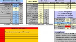
Have a good read of the datasheet and info on Carlos's snubbered supply. Peter's power supply PCBs has allowances for the snubbered supply.
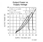
National Semi have a good design guide (used to be a spreadsheet). Have a look at what rail voltages are acceptable for 4R loads in the graph and anything over 30VDC is not good.
To cover low impedance speakers on my LM4780, I use 26VDC rails and use 100uF caps at the chip and snubbered 10,000uF on the power supply.
Have a good read of the datasheet and info on Carlos's snubbered supply. Peter's power supply PCBs has allowances for the snubbered supply.
National Semi have a good design guide (used to be a spreadsheet). Have a look at what rail voltages are acceptable for 4R loads in the graph and anything over 30VDC is not good.
Attachments
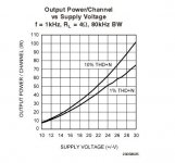
That graph only gives part of the picture as you need to see the others in the datasheet for 6R and 8R. You have to make the rail voltage suit the speaker. Here's the one for the LM3875 which shows as rail voltage goes up, low impedance capabilities fall.
Attachments
rabbitz, your quote:
"As you increase your rail voltage, the low impedance driving capabilities decrease"
If I remember correctly, Output impedance is not a function of power supply, it depends on loop gain of the opamp which is plenty for this design. As the power supply increases, the power output increase so is distortion and it does NOT mean the output impedance increases.
For what I read here LM3875 does not have enough current to drive low load eg 4 ohms and lower. LM4870 is a dual LM3886 and each LM3886 can drive a 4 ohm load. Daniel and others believe so, in other postings I read.
I have to agree with rabbitz and AndrewT. I build two mono blocks using the LM3876 and with out any preamp it just didnt "sound right". Then I built a simple buffer (from Rod Elliots site) using the OPA2134 op amps with a gain of 2. After connecting the 100k pot to the buffer then the buffer to the lm3876 amp, the amp sounded much "better".
Sadly, you are hearing the limitations of your 'cloned' speakers.
I've been looking at the response curve of the tweeter, and in a number of 2.5 clones that are on the web (in the main, using the same tweeter) if its is like the one designed by Troels, then there is a very visible drop in output above 15KHz. That would sound 'closed' and 'shut in', especially if no buffer is used with long interconnects - you are then placing another low pass filter in the audio stream!
http://www.troelsgravesen.dk/download/2.5_Clone.pdf
The loose and boomy bass is because the cabinet size is acoustically tuned (i.e mainly by ear, but also has reasonable measurements), and may well be exciting room modes, especially if they are close to a rear wall (excites the primary modes more).
In a transformer coupled amp, the power output availble for the bass is reduced with reduction in frequency because of the transformer.
This is not the case with the gainclone. It's flat. If it needs to deliver 50 Watts at 10Hz, it'll do it for as long as needed assuming a correctly sized heat sink. These amps are used to derive a 50 Watt power supply for turntables, so they can drive the LF very well. The increased cap powersupply means that the amp can deliver bass transients in excess of that stated output!
So. in summary, you will hear a different presentation with a lower cap supply (that should help with the bass situation), and you will need a pre-amp to ensure that the input of the gainclone is properly driven with this speaker. These two changes will make a substantial difference to the sound.
Reducing the capacity in the powersupply will reduce the inrush current, and that means the 'soft start' circuit can be binned too!
So, in order, reduce the psu capacity (unsolder the 10k uF caps you have there), take out the 'soft start', and use a preamp/buffer before your gainclone. Then see what it can do.
Owen
if even the audiosector amps have not any such components at the input?Without the low Rs, the volume control will become a variable filter when it interacts with the filter components at the power amp input.
YES!
There will be a capacitance at the input that will be a direct product of the circuit used in the chip.
There will also be capacitance in the cables too, so even if there isnt a direct input capacitor, there will be a 'virtual' capacitor in series.
Because it's not seen, it is often forgotten...
Owen
Re: rabbitz, your quote:
output impedance and low impedance driving capability are two completely different concepts.
The chipamps have severe problems sourcing adequate current into low impedance loads.
It shows in the extracted graphs posted by Ttan98.
if one converts the output power capability of the chosen chipamp into the output Vpk and Ipk, then one begins to see the difficulty.
What is often overlooked is the effect a reactive load has on the current demand from and dissipation of the chipamp.
4ohm speakers are a demanding load and a severe 4ohm load with a load phase angle approaching 60degrees will trouble just about any single chipamp. Paralleling helps solve the problem. Lower supply rail voltage helps as well. Neither of these solutions lowers the output impedance. The first increases the available current, the second lowers the Ipk supplied to the load.
ttan98 said:"As you increase your rail voltage, the low impedance driving capabilities decrease"
If I remember correctly, Output impedance is not a function of power supply, it depends on loop gain of the opamp which is plenty for this design. As the power supply increases, the power output increase so is distortion and it does NOT mean the output impedance increases.
For what I read here LM3875 does not have enough current to drive low load eg 4 ohms and lower. LM4870 is a dual LM3886 and each LM3886 can drive a 4 ohm load. Daniel and others believe so, in other postings I read.
output impedance and low impedance driving capability are two completely different concepts.
The chipamps have severe problems sourcing adequate current into low impedance loads.
It shows in the extracted graphs posted by Ttan98.
if one converts the output power capability of the chosen chipamp into the output Vpk and Ipk, then one begins to see the difficulty.
What is often overlooked is the effect a reactive load has on the current demand from and dissipation of the chipamp.
4ohm speakers are a demanding load and a severe 4ohm load with a load phase angle approaching 60degrees will trouble just about any single chipamp. Paralleling helps solve the problem. Lower supply rail voltage helps as well. Neither of these solutions lowers the output impedance. The first increases the available current, the second lowers the Ipk supplied to the load.
owen said:Sadly, you are hearing the limitations of your 'cloned' speakers.
I've been looking at the response curve of the tweeter, and in a number of 2.5 clones that are on the web (in the main, using the same tweeter) if its is like the one designed by Troels, then there is a very visible drop in output above 15KHz. That would sound 'closed' and 'shut in', especially if no buffer is used with long interconnects - you are then placing another low pass filter in the audio stream!
http://www.troelsgravesen.dk/download/2.5_Clone.pdf
The loose and boomy bass is because the cabinet size is acoustically tuned (i.e mainly by ear, but also has reasonable measurements), and may well be exciting room modes, especially if they are close to a rear wall (excites the primary modes more).
In a transformer coupled amp, the power output availble for the bass is reduced with reduction in frequency because of the transformer.
This is not the case with the gainclone. It's flat. If it needs to deliver 50 Watts at 10Hz, it'll do it for as long as needed assuming a correctly sized heat sink. These amps are used to derive a 50 Watt power supply for turntables, so they can drive the LF very well. The increased cap powersupply means that the amp can deliver bass transients in excess of that stated output!
So. in summary, you will hear a different presentation with a lower cap supply (that should help with the bass situation), and you will need a pre-amp to ensure that the input of the gainclone is properly driven with this speaker. These two changes will make a substantial difference to the sound.
Reducing the capacity in the powersupply will reduce the inrush current, and that means the 'soft start' circuit can be binned too!
So, in order, reduce the psu capacity (unsolder the 10k uF caps you have there), take out the 'soft start', and use a preamp/buffer before your gainclone. Then see what it can do.
Owen
owen said:YES!
There will be a capacitance at the input that will be a direct product of the circuit used in the chip.
There will also be capacitance in the cables too, so even if there isnt a direct input capacitor, there will be a 'virtual' capacitor in series.
Because it's not seen, it is often forgotten...
Owen
Hi Owen,
if I understand your postings correctly then I fear you have mis-understood the science/electronics/maths.
The result is that some of your conclusions are flawed.
Do you want to Email me?
ok!YES!
But these parasitic components are part of any amp, not only the natsemi series.
Why are the gainclones considered something special?
Regards
owen said:
In a transformer coupled amp, the power output availble for the bass is reduced with reduction in frequency because of the transformer.
Which amp is transformer coupled? The Vincent? Really?
Even if it was at what frequency would there be anomalies? 5Hz?
Most reviewers mention the bass response as the amps best feature.
Andrew,
Thanks for the offer..
I suggest that a close look at the 'budget' seas tweeter commonly used for these 'clones' - they can have up to 6db drop at 20KHz dependant on the crossover topology used.
I have looked at the 'vincent' amps, and from what I can see they are a hybrid bipolar output stage with valve buffer, biased to give a higher wattage class A output than a standard A-B stage.
My comments specifically for the proaclones (and the proacs) relates to the use of an amplifier that has a transformer output (typical valve amp, but has been used with SS too).
These have a reduced wattage output at LF due to transformer core saturation, that can mask the true LF acoustic output of the speaker, and in turn help minimise the excitation of room modes. That also ignores the difference in damping factor of the amplifier...
The PDF links to Troels designing the clone itself, and to paraphrase - the cabinet volume is approximately 67 litres, but the simulations suggest 42 litres on page 10.
The fact that the speaker output is circa 10 ohms for Troels design, mean the rail voltages should be ok, and the phase shifts are + - 35 degrees and have smooth changes above 100 Hz, as would be expected of a stuffed transmission line design.
Juergen,
The input capacitance (as opposed to the input capacitor) requires current to drive it, and it is an integral part of any amplifier stage. It has a value that is a part of describing the input impedance.
Impedance is different to resistance, in that is varies with frequency, and is electrically described using an equivalent circuit comprised of an inductor, resistor, and capacitor.
As the impedance varies, the output of the buffer must be able to vary the current to maintain the voltage (as these are voltage amplifiers) at the main amplification stage, otherwise the voltage will drop. This voltage 'drop' at that frequency, will be audible, because in effect the 'volume' has been lowered.
Now onto the gainclone. In the gainclone, it can be configured to have a relatively high input impedance, so these effects are reduced. This lead many to use (and lots of people like them like this) just a simple potentiometer as the attenuator in the circuit.
However, this means that you are dependant on the quality of the source buffer to be able to maintain the current to drive not only the capacitance of the cabling, but into the input impedance of the amplifier. It must also be able to do this through the resistance of the attenuator too.
The capacitance of the cable, and the input impedance are in parallel, so will be summed! This is what produces the 6db/octave low pass first order filter to your amp, and is what produces the characteristic HF roll-off.
This 'problem' is obviously exacerbated by long interconnects (source - attenuator - power amp is typically 2 meters!), and a weedy output buffer on your source.
The most dramatic demonstration of this is in a badly designed triode amplifier, where the miller capacitance is large, and the input stage is current poor - for example a 12ax7 driving a 6c33.
To equate that to your system, the 12ax7 is equivalent to the output from your source, and the 6c33 is equivalent to your power amp. In a valve amp, in those cases, you insert a 'driver' stage to provide the necessary current - and with a gainclone, an active preamp, or buffer does exactly the same job.
It ensures that there is sufficient current to maintain linearity across the audible spectrum.
Owen
Proacs are noted as valve(tube) amp friendly, because of benign impedance curves, higher impedance overall than many designs. They are also engineered to have a tightly managed frequency response, and offer good LF extension. This LF extension is rarely fully encountered with a valve amp, simply because the output transformer core cannot swing enough magnetic flux (it in effect goes into magnetic 'clipping'), and so output falls below a common 40 or so Hz, but there are exceptions to this (OTLs, and massively engineered designs).
So reduced LF output from the amp, means reduce LF output from the speakers, that means less energy available to excite LF room modes.
Ok?
Owen
So reduced LF output from the amp, means reduce LF output from the speakers, that means less energy available to excite LF room modes.
Ok?
Owen
To: Andrew T
Please read my posting I DID NOT SAY the follow:
"As you increase your rail voltage, the low impedance driving capabilities decrease"
rabbitz did.
Also, you said
"It shows in the extracted graphs posted by Ttan98."
Rabbitz posted it I did not.
So please read my posting carefully.
Each amp has 0.1ohm connected to it if both of them are connected in parallel, that increase the output impedance by a small amount and decrease the driving ability.
oops
Hi Rabbitz, Ttan98 and all,
sorry for the erroneous attribution. I substituted Ttan98 for Rabbitz. Got myself a bit mixed up.
The general meaning is hopefully still understood.
Ttan98 has got it wrong.
I did read Ttan98's posting and other than the wrong attribution my message is the same.
Hi Rabbitz, Ttan98 and all,
sorry for the erroneous attribution. I substituted Ttan98 for Rabbitz. Got myself a bit mixed up.
The general meaning is hopefully still understood.
Ttan98 has got it wrong.
I did read Ttan98's posting and other than the wrong attribution my message is the same.
Yes Andrew, I knew what you meant.
Ttan98, in my illustration I wasn't referring to the output impedance of the amp but to it's ability to drive low impedance loads, hence the graphs from the datasheet. Although the LM3875 is not relevant to this, it does show how these chips react to voltage vs impedance load. It's also on the LM4780 datasheet but on separate graphs.
I've played around with Peter's LM4780 kit in stereo and parallel mode and ended up with a stereo module which is used in a workshop test system. Tests are done often with low impedance speakers and I can tell you with higher voltage rails the chip is not the happiest camper under these loads. That's why I dropped the rail voltage so it can accommodate all the speakers I try and a side benefit is running much cooler which is important as the workshop is not air conditioned on hot days. I lose power by doing this but it's working well within it's limitations.
- Status
- This old topic is closed. If you want to reopen this topic, contact a moderator using the "Report Post" button.
- Home
- Amplifiers
- Chip Amps
- gainclone dissapointment