I have a pair of Amplimo 3.5k toroidal output transformers that are extremely compact for their 40W rating, so I was thinking of using them in a max-power 6" cube amp. I like the tall, skinny form factor of the 18GB5s I have kicking around, so I was thinking of those for the output tubes. The ouput transformers will take practically no room tacked inside the case.
The big problem is choosing between drive schemes. The 6GB5/EL500 has a relatively high screen grid rating of 275V - this and the curves available tend to indicate that it would make a good showing as a pure pentode. The other possibility would be pure screen drive or g1/g2 drive. I suspect that the relatively high screen voltage rating means lower screen sensitivity, so that pentode mode or g1/g2 drive would be more attractive. Anyway, I'll be tracking developments here to see what can be done. The prospect of a 6" cube with SMPS and 40-50W of capability (at least on peaks) is very attractive, so much so that it may displace another project.
The big problem is choosing between drive schemes. The 6GB5/EL500 has a relatively high screen grid rating of 275V - this and the curves available tend to indicate that it would make a good showing as a pure pentode. The other possibility would be pure screen drive or g1/g2 drive. I suspect that the relatively high screen voltage rating means lower screen sensitivity, so that pentode mode or g1/g2 drive would be more attractive. Anyway, I'll be tracking developments here to see what can be done. The prospect of a 6" cube with SMPS and 40-50W of capability (at least on peaks) is very attractive, so much so that it may displace another project.
I guess that there is new life in this thread now! The clip lead and turret board furball that I tested in posts 29 and 30 has been stripped for parts. I performed a few experiments on it, and learned a few things, but it was too limited. I have played with Petes red board for several months, learning quite a lot, and discovering its limitations. Many screen drive experiments revealed high efficiency and power output, some tube melting limtations exist there too. As I mentioned in the red board thread, I need a new board, but I don't quite know what it is yet. So, I decided that a little prototype system that could be warped into an amplifier is what I need.
I thought about it for a while and this is what I came up with. It bears some resemblances to yours mechanically. The circuit is totally different. Mine is a cross between the red board and the circuit in post 29 with a mosfet replacing the triode.
Since I am trying to bring together several concepts that I have learned over the past 2 years, and test a few new theories, I call this the "grand unified theory amp".
The GUT amp! I like it...
Scaled grid drive sure seems to be promising at 1/2 the drive voltage vs. screen drive. I'm having some difficulty reproducing your screen drive power out figures for the same B+ and using the same OPT. I'm getting 70W where you were getting 90W for 600V and 6K6 plate-plate, and I'm using a beefier tube (12DQ6) to boot. I'll need to check my plate swing next time I heat it up. You were measuring power across the 8 ohm load resistor, correct?
I'll be very interested in the effect of g1 current on your resistor divider to see if my extra g1 followers are buying me anything.
My circuit is also a lot like the DCPP amp except I have gyrators instead of plate resistors, and I use a depletion MOSFET on the other side of the inverter instead of a pentode. The plate to plate feedback works exactly the same way. We should be able to compare results.
Cheers
Michael
I have a pair of Amplimo 3.5k toroidal output transformers that are extremely compact for their 40W rating, so I was thinking of using them in a max-power 6" cube amp. I like the tall, skinny form factor of the 18GB5s I have kicking around, so I was thinking of those for the output tubes. The ouput transformers will take practically no room tacked inside the case.
The big problem is choosing between drive schemes. The 6GB5/EL500 has a relatively high screen grid rating of 275V - this and the curves available tend to indicate that it would make a good showing as a pure pentode. The other possibility would be pure screen drive or g1/g2 drive. I suspect that the relatively high screen voltage rating means lower screen sensitivity, so that pentode mode or g1/g2 drive would be more attractive. Anyway, I'll be tracking developments here to see what can be done. The prospect of a 6" cube with SMPS and 40-50W of capability (at least on peaks) is very attractive, so much so that it may displace another project.
I like concept amps

Here are my thoughts on tube suitability for various drive methods.
The high screen rating does imply reduced sensitivity, butI think the g2 power sensitivity can be evaluated precisely, at least in relative terms, by taking gm/g1g2mu.
i.e. the power sensitivity of g1 is a function of gm, and the power sensitivity of g2 is gm divided by the g2/g1 voltage ratio. A high gm tube that also has high mu might be OK, but the best candidates IMO are the ones with good gm AND low mu.
And apparently the relative power sensitivity of scaled drive is about 2*(gm/g1g2mu) or 2X that of pure screen drive.
Another figure of merit I have been using with Schade current mode feedback output stages is effective plate resistance. For g1-drive this is approximately 1/gm. For screen drive, it's about g1g2mu/gm, and for scaled drive it seems to be ~g1g2mu/(2*gm). For a 6DQ6 it's 4.4/(2*7300) or 290 ohms. Without any global feedback, that suggests a high-ish load (1650 ohms or 6K6 plate-plate sounds reasonable for good DF)
Cheers,
Michael
I'm getting 70W where you were getting 90W for 600V and 6K6 plate-plate, and I'm using a beefier tube (12DQ6) to boot.
Don't remember the exact configuration since I am at work now, but many of my screen drive experiments and red board experiments were done at 3300 ohms. Most of my screen drive experiments were done before I got the big power supply, so I was at 550 volts. Put an 8 ohm load on the 16 ohm tap with those transformers. They seem to work well that way. Many of the extreme power (over 150 watts) experiments were done using the Plitrons at 2500 ohms.
OK, I just read the screen drive thread where it says I got 90 watts at 6600 ohms with the big power supply. My measurements are usually correct since that is what I do for a living, so I must assume that the 6BQ6's can really crank out this much power, so there is only one thing left to do. Crank up another set!
It will be a few days before I have my board ready for smoke testing, but I have already decided the 6BQ6 will be my first test subject. Why? Because I have over 100 of them! I found a few less than perfect 6DQ6's and even some 6146's (request from another thread) so I should have some new test data soon. Maybe next weekend.
It will be a few days before I have my board ready for smoke testing, but I have already decided the 6BQ6 will be my first test subject. Why? Because I have over 100 of them! I found a few less than perfect 6DQ6's and even some 6146's (request from another thread) so I should have some new test data soon. Maybe next weekend.
Question:
Why explicitly deny yourself the additional gain of g1? Look at that: there's a *voltage divider*! It's actively reducing your gain!
This is silly and I see no virtue in it, in terms of biasing or AC response. Screen drive in general is plagued not only by screen current (which is considerable in sweep tubes) but by miller effect as well, something which is nicely shielded for you by the screen grid in pentode mode.
Tim
This is silly and I see no virtue in it
I could say the same thing about the class D tube amp! In reality I have been building tube amps for over 40 years. I really don't need to make any more cookie cutter amps. It's time to do something different, but something different that may actually work better than the same old stuff.
Screen drive in general is plagued not only by screen current (which is considerable in sweep tubes) but by miller effect as well, something which is nicely shielded for you by the screen grid in pentode mode.
True, but Miller and grid current aren't a problem if you use a mosfet follower to feed the grids. If you are sand-a-phobic use a cathode follower.
I (and others) have seen the virtues of screen drive. It is possible to get low distortion (minimal crossover) at very low idle currents. It is also possible to achieve high (75+%) plate efficiency affording high power output from small tubes. Screen drive does have a fatal flaw. On signal peaks the screen voltage can go very high at the instant the plate voltage is very low. Tube arcs and melted grids are possible. Yes I have melted a few tubes.
It has been postulated that driving both grids may overcome this problem. Will it work? I don't know. Michael has simulations that says yes. My experience with LT spice on tube circuits shows that this doesn't guarantee success, but a simulation that fails predicts failure fairly well.
Why explicitly deny yourself the additional gain of g1? Look at that: there's a *voltage divider*! It's actively reducing your gain!
Yes, it is. For a reason. I am not one to rely completely on simulations or the word of others. Call me stubborn, but I need to try something myself, so I tied G1 to G2 and drove them with a mosfet. BANG happened, not once but three times! OK, I have come to the conclusion that G1 draws all the current and blows the mosfet, and a bigger mosfet blows the coating off the cathode!
A preliminary experiment (post #29) revealed that driving the screen while also driving G1 but keeping G1 negative throughout the entire signal swing (for simplicity, no sand) resulted an a working, but not totally optimum amp. It proved (to me at least) that this concept has merit and deserves further experimentation.
My "copper board" will be used to perform several experiments involving driving both grids. I will eventually have the ability to drive each grid independently with its own AC and DC level controls. Adjustable normal and cross coupled Schade feedback too.
Is this a waste of time? I won't know until I am done. It's safe to assume something will go BOOM!
I'm with George on the merits here. This is an approach that derives from trying to fixup g2 drive problems, while still retaining some of it's "advantages" hopefully. Clearly one can complain of the absurdity of g2 drive, but many DIYers have made those and reported good results. So, this is an interesting excercise, something different, maybe good.
Tim's complaint though gives me an idea. What if we drive g1's only and bootstrap drive the g2's from cross-coupled plates or UL taps. Sort of self powered g2 drive. Likely some compromise in linearity and Rout, but no gain waisted then. Another experiment for the que. Have to check for loop gain and stability that way.
By the way, I've gotten some Edcor OTs in too, 100 Watt 3.3K, 4.2K, 5K , working up some sort of test bed too. Likely use 6GF5s for drivers (770 V B+ plate rating should handle about anything for g2. 6HJ5s for outputs, Schaded or CFB mode, but others to try as well like 21HB5, 35LR6, 17KV6, 6CB5 and 12GE5.
Last edited:
So far, things aren't being made easy for me, in that the mu data isn't given in the data sheets I have so far for the 6GB5/EL500. I may just say "screwit", and bull through with a straight pentode approach to get to a finished amp. The EL500 data sheet I have on hand has enough pentode curves at various screen voltages to make this a straightforward exercise, and there's always room for a little Schade action (my Amplimo toroids have no UL taps, and no, I'm not paying 200+ Euro per transformer to get them...). Anyway, with a cascoded jfet front end (I have an extra board from my "Lil Devil" project) and mosfet drivers, this could be a very robust and compact AB2 amp. 40W/per in a 6" cube - I like confounding people. When I brought my 1625-based "Shrine" amp (my first 6" cube with a SMPS) to the first Burning Amp, there were people that asked me if it was a power supply - quoting various individuals, mu ha ha...
I'm with George on the merits here. This is an approach that derives from trying to fixup g2 drive problems, while still retaining some of it's "advantages" hopefully. Clearly one can complain of the absurdity of g2 drive, but many DIYers have made those and reported good results. So, this is an interesting excercise, something different, maybe good.
Tim's complaint though gives me an idea. What if we drive g1's only and bootstrap drive the g2's from cross-coupled plates or UL taps. Sort of self powered g2 drive. Likely some compromise in linearity and Rout, but no gain waisted then. Another experiment for the que. Have to check for loop gain and stability that way.
By the way, I've gotten some Edcor OTs in too, 100 Watt 3.3K, 4.2K, 5K , working up some sort of test bed too. Likely use 6GF5s for drivers (770 V B+ plate rating should handle about anything for g2. 6HJ5s for outputs, Schaded or CFB mode, but others to try as well like 21HB5, 35LR6, 17KV6, 6CB5 and 12GE5.
Cause crossed UL drive sucks BIG screen currents contrary to phase dot.
Already simmed that configuration to death, for entirely different reasons.
Come to a conclusion that you lose more than you can get back. Maybe
I'm just missed something oblivious, but I don't think so...
Don, you say ",but no gain wasted then." Yet current gain IS wasted...
I saw no problems with stability, but I was also abusing cathode feedback
from 0 and 16 taps, with 4 to the tail. Without such feedback is it stable?
Heck if I know...
Last edited:
On page 5 of the 11 page Phillips data sheet for the EL500, you can just read off the Mu from the graph versus plate current. Pick a current level, then jot down the diff. in g1 voltage versus diff. in g2 voltage for that current. About 6.6 Mu.
http://scottbecker.net/tube/sheets/030/e/EL500.pdf
------------------------------------------------------------------------------------------------
"Cause crossed UL drive sucks big screen currents contrary to phase dot.
Already simmed that configuration to death, for entirely different reasons.
Come to a conclusion that you lose more than you can get back. Maybe
I'm just missed something oblivious, but I don't think so... "
Likely still have to use Mosfet drivers for the g2's. And the g2 drive has to be less than 1/Mu of plate voltage maybe, or something? I guess you have to figure the plate swing into the OT Zpri, then figure back to what g2 drive would produce that. Drive has to be less than that for stability. Which is likely a lower drive level than the raw UL taps provide I would guess. The thing will really go unstable if you remove the speaker load though. Poooffffff! Hmmm, well Schade fdbk could set a finite gain I guess (regardless of load Z), so g2 self drive just has to be set low enough to avoid self oscultation.
Last edited:
Likely some compromise in linearity and Rout, but no gain waisted then.
When you are playing with pentodes gain is easy to get. Voltage swing is a bit harder to come by, which brings us back to gain....in the output stage. Then we propose to reduce said gain by local feedback. Obviously there are trade offs to be made here. Some would worship the simulator, but that relies on accurate tube models for tubes that are used in a manner that they weren't intended to be used. So, I will just build it and blow it up a few times.
By the way, I've gotten some Edcor OTs in too, 100 Watt 3.3K, 4.2K, 5K , working up some sort of test bed too.
OK, there are now 3 of us trying this. Either we are going to make it work, or we are ALL wasting our time and parts!
others to try as well like 21HB5, 35LR6, 17KV6, 6CB5 and 12GE5.
I have some of all of those, 6GF5's too, but I would really know how much power I could get out of the little 6BQ6GT's WITHOUT melting them!
this could be a very robust and compact AB2 amp. 40W/per in a 6" cube
That would be cool. I have given up on making an SMPS my attempts only seem to summons the smoke monster, the fire gods, or both. So I decided to make a "Tube Cube" It is 4 times larger than yours at 12", uses a conventional power supply (Antek toroid) and two Simple P-P boards for 60 WPC. The real difference, mine weighs almost 30 pounds. Looks cool though. Pictures soon, its not quite finished yet.
Come to a conclusion that you lose more than you can get back.
Well, from experience, on 6CW5's you will lose....the screen grid! Also it sounded really nasty right before it blew up too.
Need cheap power see this thread.
http://www.diyaudio.com/forums/tubes-valves/169867-10-pounds-power-15-a.html
http://www.diyaudio.com/forums/tubes-valves/169867-10-pounds-power-15-a.html
I made some more measurements and my plate swing is 480V peak for a 580V plate-cathode voltage. So I'm only swinging down to 100V plate-cathode at clipping. Clipping occurs at 160V pk-pk g2 drive, but the driver is capable of 200V pk-pk before it clips. The driver's pushing harder but nothing's coming out...
Vg2 = 8.5V idle, 160V pk-pk drive at output clipping, 200V pk-pk at driver clipping
Vg1 = -2V idle, 36V pk-pk drive at output clipping, 44V pk-pk at driver clipping
Idle current is 20mA/side at 600V plate-cathode.
All I can imagine is that I'm hitting some limit in the output stage that prevents further plate swing. I haven't checked the total cathode current but maybe the total g1 + g2 current is diverting plate current. Something to think about.
Maybe I'll configure it in regular tetrode mode and see how that works. Hmm I can also get another 20V pk with the current driver; maybe I can try to reduce the g2/g1 ratio, increasing the g2 drive swing ralative to g1, and see if I get more plate swing that way.
Michael
Last edited:
I made some more measurements and my plate swing is 480V peak for a 580V plate-cathode voltage. So I'm only swinging down to 100V plate-cathode at clipping. Clipping occurs at 160V pk-pk g2 drive, but the driver is capable of 200V pk-pk before it clips. The driver's pushing harder but nothing's coming out...
Vg2 = 8.5V idle, 160V pk-pk drive at output clipping, 200V pk-pk at driver clipping
Vg1 = -2V idle, 36V pk-pk drive at output clipping, 44V pk-pk at driver clipping
Idle current is 20mA/side at 600V plate-cathode.
All I can imagine is that I'm hitting some limit in the output stage that prevents further plate swing. I haven't checked the total cathode current but maybe the total g1 + g2 current is diverting plate current. Something to think about.
Maybe I'll configure it in regular tetrode mode and see how that works. Hmm I can also get another 20V pk with the current driver; maybe I can try to reduce the g2/g1 ratio, increasing the g2 drive swing ralative to g1, and see if I get more plate swing that way.
Michael
Hmm earlier in this very thread may be the answer
http://www.diyaudio.com/forums/tube...aled-drive-strawman-design-2.html#post2135104
Don's curve with my loadline leads me to only expect 100Vak minimum on this load line. And the explanation is somewhat similar to what I have been thinking.
The cathode current curves tell the story I think:
http://www.diyaudio.com/forums/tube...scaled-drive-strawman-design.html#post2133023
Showing 300mA cathode current peaks for 200mA plate current peaks, and apparently not showing the additional 60mA g1+g2 current spikes on top of that. If these ratios hold for 350mA peak plate current, the max cathode emission capability is probably being exceeded and I need a tube with a bigger cathode. More gm couldn't hurt either...
Oops, bottom left corver of the graph should be labeled "0"
Attachments
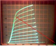
Showing 300mA cathode current peaks for 200mA plate current peaks, and apparently not showing the additional 60mA g1+g2 current spikes on top of that. If these ratios hold for 350mA peak plate current, the max cathode emission capability is probably being exceeded and I need a tube with a bigger cathode. More gm couldn't hurt either...
OR
Maybe the solution is to reduce the peak g1 current. I can try to offset g1 to negative bias and increase the g2 positive bias, keeping the AC drive voltages and levels the same as now. This will reduce the g1 current and may get the Vak(min) back down to 50V as in pure g2 drive operation. for example, g2 could be biased at +80V and run with 160V P-P drive, while g2 might be biased at about -20V or thereabouts, which would prevent g1 from needing to go positive.
Time to think up a circuit for adjustable g1 offset...
Many screen drive proponents tie G1 to the cathode. Most of my experiments revealed more power with a lower distortion with a small negative voltage on G1 (-15 volts or so). This does however subject G2 to more abuse since it must go higher on positive peaks. Result...a nuclear fireball inside the tube, but I was extracting over 100 watts out of some tiny tubes continuously. Occasional music peaks should be fine.
I will be using a seperate mosfet for each grid with a DC adjustment and an AC level control for each.
I will be using a seperate mosfet for each grid with a DC adjustment and an AC level control for each.
I found scope pictures of some of my screen drive experiments in an old thread. See posts #104 and 105 in this thread. Plate hits nearly zero volts. More screen drive stuff scattered throughout the thread.
http://www.diyaudio.com/forums/tubes-valves/128533-tube-sale-aes.html?highlight=tube+sale+aes
http://www.diyaudio.com/forums/tubes-valves/128533-tube-sale-aes.html?highlight=tube+sale+aes
I will be using a seperate mosfet for each grid with a DC adjustment and an AC level control for each.
How would you label them on a guitar amp?
- Status
- This old topic is closed. If you want to reopen this topic, contact a moderator using the "Report Post" button.
- Home
- Amplifiers
- Tubes / Valves
- G1=G2/mu Scaled Drive Strawman Design