Christer said:
I would tend to agree with Sloane that for a diff pair it is
actually Vbe matching that is important. Matching also hfe may
be beneficial in minimizing offsets
I assume you are referring to Slone. In his book you will see
that for BJT's he stresses the value of beta matching, and does
not mention Vbe matching that I can find.
Now if we're talking about tubes or FETs or MOSFETs, all
bets are off, and control voltage matching becomes very
important.
Nelson Pass said:
I assume you are referring to Slone. In his book you will see
that for BJT's he stresses the value of beta matching, and does
not mention Vbe matching that I can find.
True, he spells his name "Slone", not "Sloane". My fault.
Quite to the contrary of what you say, he does state clearly in
his power amp. book that for the diff pairs, it is Vbe matching
that is important, not hfe matching. He makes the claim without
any attempt to back it up, except saying that it is about
semiconductor physics. I had never thought of this before, so
I sat down and tried to verify his claim. Using the transport
model for BJTs it turned out that a diff pair can be considered
essentially as a transconductance amplifier, that is, it is voltage
controlled rather than corrent controlled (assuming rasonable
source impedances, of course). This is because both transistors
have a floating common voltage reference point at their
emitters. I am sure this is nothing new at all for EEs (Nelson,
you have probably just worked with MOSFETs for too long, so
you have forgotten
") ). These mathematical exercises also give
). These mathematical exercises also givemore insight into the nice linearity properties of diff pairs.
halojoy said:
As a different pair try to match the input on both sides,
they act like a balance, that weigh things.
So this is why both sides have to be identical.
Preferable in all aspects and have the same working condition.
Like current and voltage.
This is very hard to do, even if you have same b-e voltage and hfe.
They can behave different around that messuring point.
See my answer to Nelson. Vbe matching is important, hfe
much less so, since it only affects the offset currents.
Hi Christer,
>See my answer to Nelson. Vbe matching is important, hfe
>much less so, since it only affects the offset currents.
Nice to see you EEs pondering this subject.
But for a fool like me, who just likes to build the Aleph 5 in the best possible way, how can I match these?
I have only got a digital multimeter with the possibilty to measure hFE...
Any advice?
Thanks,
Lucas
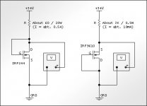
hook up the transis with SOURCE to ground and use only one half of the split supply.
Have a little variable voltage supply at the GATE.
It can be as simple as a pot parallell with a zener diode
Put a suitable resistor, one that gives reading below 2.000 voltage for the current between V+ (V- for PNP) and the DRAIN
Slowly increase the voltage potentiometer, until voltage drop over resistor is corresponding to the desired current.
When it does, messure the voltage at the GATE.
If you use a Rg resistor (this should always be put as close to the gate as possible)
you can messure not on the gate directly,
but on the pot.
When the readings are stable and does not change any more, that is the messurement to be used. (the temp is then constant, almost)
I would find matching Vgs, as follows.Lucas_G said:... just likes to build the Aleph 5 in the best possible way, how can I match these?
I have only got a digital multimeter ...
JH
Attachments
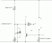
As a test using potentiometer as voltage source, reguires repeated adjusts and messurments, I tried to make circuit that will work in a more Automatic way.
Select the resistor for 6 Volts, without MOS connected.
Turn Power off.
Select resistor for current. I=0.65 Volt/R.
Connect MOS, and power on.
Put a voltmeter across A - S.
When the reading is stable and does not change any more, that is the messurement to be used. (the temp is then constant, almost)
Attachments
Just use the circuit that jh6you posted, this is the same circuit as used by Nelson Pass and while it has it's limitations, it is perfectly fine for our purposes. Yes the absolute current will vary a little with Vgs, but when the Vgs matches for 2 different MOSFETs, the relative current will also be the same.
halojoy said:As a test using potentiometer as voltage source, reguires repeated adjusts and messurments, I tried to make circuit that will work in a more Automatic way.
Select the resistor for 6 Volts, without MOS connected.
Turn Power off.
Select resistor for current. I=0.65 Volt/R.
Connect MOS, and power on.
Put a voltmeter across A - S.
When the reading is stable and does not change any more, that is the messurement to be used. (the temp is then constant, almost)
If this is for IRFPxxx you need to put the FET on a heatsink to do this unless you want to wait until it is stable at it's own death.
/UrSv
1000mA on irfp240 for 30 secs isnt enough to kill it, i tested them on this current and they were fine.
Fets were matched ok (but you must read vgs exactly after 30 secs if you want proper resoults), because the guys i sold some to matched them again, because they wanted to build a3 instead of a5 for which i was matching them for, and they said that they were already matched very good.
Fets were matched ok (but you must read vgs exactly after 30 secs if you want proper resoults), because the guys i sold some to matched them again, because they wanted to build a3 instead of a5 for which i was matching them for, and they said that they were already matched very good.
Christer said:Quite to the contrary of what you say, he does state clearly in
his power amp. book that for the diff pairs, it is Vbe matching
that is important, not hfe matching.
Perhaps I have the newly revised edition.
In it, Slone makes a big point of Vbe matching in the section
on current mirrors which precedes his discussion of diff pairs
and then goes on to talk about the need for high betas in
BJT diff pairs to avoid DC offset.
The main point here is that matching Vbe in diff pairs is
generally unnecessary.
As stated in one of my earlier posts
I advice to try to immitate the condition under which the device
is going to operate.
One important condition is the chip temp. (see thread "heat issues")
I have already mentioned the use of heatsink, how impractical
and the time consuming process that this can be.
But I myself, have a lot of time.
I seldome repeat myself, just because likings in doing so, does not correspond to my personality.
BJT matcing cont'd
Well, Slone have a tendency to spread things out over the
whole book, so you have to look at several places and try to
lay the puzzle. Looking back now, I see that he does not state
things quite as clearly as I remembered. In the subsection on
current mirrors he says that degeneration is necessary since
it is difficult to find transistors that are matched for beta
and Vbe, thereby implying that both these parameters should be
matched. Later, when discussing diff pairs, he says that the
current mirror transistors should be beta matched, and that
denegeration takes care of the Vbe mismatch. For the diff pairs
themselves, he seems not to say right out that they should be
Vbe matched. However, he says that according to the physics
beta does not matter, but Vbe does. Later he argues that Vbe
"matching" is taken care of by degeneration and that beta
should be matched to minimize the offsets. That is, he is rather
unclear and also a bit inconsistent.
Of course, what matters is not what Slone says, but how things
really are. The only reason I brought up Slone was that he
made me realize that also Vbe matching must be considered.
The main point here is that matching Vbe in diff pairs is
generally unnecessary. [/QUOTE]
I have done some more thinking and some simulations now.
My theoretical analysis was partly flawed, since I assumed that
the offsets could be neglected for balance. That was not a
valid assumption. Having now done some SPICE
simulations of Q points under varying conditions, it turns out
that both Vbe and beta matching are important, and it depends
on the circumstances which one is most important.
I consider a diff pair with no collector load, bias resistors to ground on the bases and a common current sink on the emitters.
I assume that SPICE parameters that matter here are
the saturation current IS (which is what we control with
Vbe matching) and the current gain BF (ie. beta or hFE).
Assuming IS = 1fA and BF = 100 (ie. a typical small-signal
transistor) I simulated the effect of doubling either of these
parameters for one transistor in the pair for varying values
of the bias resistors. It turns out that for bias resistors of
1kOhm or lower, errors in IS dominate heavily and for values
of 10kOhm or more, errors in BF dominate heavily. This means
that Vbe matching is much more important than beta matching
for low values of the bias resistors and beta matching more
important for high values. Of course, such low values as 1kOhm
may not be so common.
If we consider a transistor with BF = 1000, that is, a very high
gain transistor, the behaviour remains, but the crossover
point moves by a factor 10. That is, Now Vbe matching is the
more important one for bias resistors of 10kOhm or less and it
can hardly be neglected for values below 100kOhm, while beta
matching is rather unimportant for values below 10kOhm.
It seems that in most practical cases we should match both
Vbe and beta.
Adding emitter degeneration decreases the effects of bad
matching as expected, but the pattern above remains. Vbe
matching is still the more important one for small bias resistors
and beta matching for large ones.
Sorry for being so lengthy, but current mirrors remain. I never
understood why Slone thinks these should be beta matched,
but I see now that he probably thinks they should be Vbe
matched too, he just doesn't say so clearly. Simulations
confirm that beta matching is unimportant here, while Vbe
matching is very important, although emitter degeneration
can help a lot. Slone seems to be wrong here, at leas in the
version of the book I have, if we have different ones.
Nelson Pass said:
Perhaps I have the newly revised edition.
In it, Slone makes a big point of Vbe matching in the section
on current mirrors which precedes his discussion of diff pairs
and then goes on to talk about the need for high betas in
BJT diff pairs to avoid DC offset.
Well, Slone have a tendency to spread things out over the
whole book, so you have to look at several places and try to
lay the puzzle. Looking back now, I see that he does not state
things quite as clearly as I remembered. In the subsection on
current mirrors he says that degeneration is necessary since
it is difficult to find transistors that are matched for beta
and Vbe, thereby implying that both these parameters should be
matched. Later, when discussing diff pairs, he says that the
current mirror transistors should be beta matched, and that
denegeration takes care of the Vbe mismatch. For the diff pairs
themselves, he seems not to say right out that they should be
Vbe matched. However, he says that according to the physics
beta does not matter, but Vbe does. Later he argues that Vbe
"matching" is taken care of by degeneration and that beta
should be matched to minimize the offsets. That is, he is rather
unclear and also a bit inconsistent.
Of course, what matters is not what Slone says, but how things
really are. The only reason I brought up Slone was that he
made me realize that also Vbe matching must be considered.
The main point here is that matching Vbe in diff pairs is
generally unnecessary. [/QUOTE]
I have done some more thinking and some simulations now.
My theoretical analysis was partly flawed, since I assumed that
the offsets could be neglected for balance. That was not a
valid assumption. Having now done some SPICE
simulations of Q points under varying conditions, it turns out
that both Vbe and beta matching are important, and it depends
on the circumstances which one is most important.
I consider a diff pair with no collector load, bias resistors to ground on the bases and a common current sink on the emitters.
I assume that SPICE parameters that matter here are
the saturation current IS (which is what we control with
Vbe matching) and the current gain BF (ie. beta or hFE).
Assuming IS = 1fA and BF = 100 (ie. a typical small-signal
transistor) I simulated the effect of doubling either of these
parameters for one transistor in the pair for varying values
of the bias resistors. It turns out that for bias resistors of
1kOhm or lower, errors in IS dominate heavily and for values
of 10kOhm or more, errors in BF dominate heavily. This means
that Vbe matching is much more important than beta matching
for low values of the bias resistors and beta matching more
important for high values. Of course, such low values as 1kOhm
may not be so common.
If we consider a transistor with BF = 1000, that is, a very high
gain transistor, the behaviour remains, but the crossover
point moves by a factor 10. That is, Now Vbe matching is the
more important one for bias resistors of 10kOhm or less and it
can hardly be neglected for values below 100kOhm, while beta
matching is rather unimportant for values below 10kOhm.
It seems that in most practical cases we should match both
Vbe and beta.
Adding emitter degeneration decreases the effects of bad
matching as expected, but the pattern above remains. Vbe
matching is still the more important one for small bias resistors
and beta matching for large ones.
Sorry for being so lengthy, but current mirrors remain. I never
understood why Slone thinks these should be beta matched,
but I see now that he probably thinks they should be Vbe
matched too, he just doesn't say so clearly. Simulations
confirm that beta matching is unimportant here, while Vbe
matching is very important, although emitter degeneration
can help a lot. Slone seems to be wrong here, at leas in the
version of the book I have, if we have different ones.
You present your argument like a gentleman.
In the case of the current mirrors (undegenerated) the Vbe
becomes critical because any mismatch severely unbalances
the value of the results. The effect is sufficiently severe, in
my opinion, that degeneration is wise even when the devices
are well matched.
In the case of the diff pair biased by a current source, the
circuit which follows and the feedback loop will generally
determine the amount of current sharing, and we need only
worry about the offset voltage which occurs.
Assuming that the amplifier is set up so that it wants 1/2
of the current fed to the diff pair, the difference in Vbe will
be the mismatch of the devices, and will show up at the output
times the DC gain of the amplifier. I expect that a mismatch
as large as 10 mV out of ~700 mV is reasonable.
Most designs operate at unity at DC, and if the mismatch is
10 mV, then we would expect a 10 mV offset.
I appreciate that some consider 10 mV a large amount of offset.
In my designs I consider myself doing well to get 50 mV.
Nelson Pass said:You present your argument like a gentleman.
Oh, I don't know. I am just a scientist who has gone astray
on this forum and cannot help keeping some of his professional
habits of wanting to find the truth about things.
I hope you realize that I am not concerned with who is
right or wrong but with what is right or wrong.
In the case of the current mirrors (undegenerated) the Vbe
becomes critical because any mismatch severely unbalances
the value of the results. The effect is sufficiently severe, in
my opinion, that degeneration is wise even when the devices
are well matched.
We agree on current mirrors.
In the case of the diff pair biased by a current source, the
circuit which follows and the feedback loop will generally
determine the amount of current sharing, and we need only
worry about the offset voltage which occurs.
For open loop, no. For closed loop, yes, the feedback will
obviously affect the balance.
Assuming that the amplifier is set up so that it wants 1/2
of the current fed to the diff pair, the difference in Vbe will
be the mismatch of the devices, and will show up at the output
times the DC gain of the amplifier. I expect that a mismatch
as large as 10 mV out of ~700 mV is reasonable.
Not quite sure what you mean here. It seems like an over-
simplification of the theory, but I agree that it is interesting to
look at the closed-loop case and the output offset. I am also
not sure where you fit beta matching into this? Maybe you
assume that we have already matched beta and so only
consider the remaining Vbe mismatch? Guess that is what you
mean.
The theoretical equations are somewhat tricky to work with,
so I did some more simulations. I considered what offset voltage
at the output is necessary to bring the diff pair back into balance
(equal collector currents) for mismatched transistors. The results
are similar to my previous ones, but are interesting since we now
get abolute numbers, not relative ones. It turns out that if one
transistor has twice the IS of the other one, it takes 17.9mV of
output offset to get balance, regardless of the other parameters.
If it instead has twice the beta of the other transistor, the
required offset voltage depends heavily on other circumstances,
like bias resistors and Q current. however, in most reaonable
cases the offset required by this beta mismatch is smaller or
on the order of 17.9mV. Only if we have collector currents of
several mA and transistor beta around 100 at most (200 for the
mismatched one) and bias resistors of at least 10kOhm do
we get larger offsets. Sure this may sometimes be the case, but
in most cases it still seems that Vbe mismatching would require
at least as big offsets as beta mismatching. One intersting thing
to consider, howver, is what the spread of IS is for ordinary
transistors. While beta often varies by a factor 3, perhaps IS
is more precise, but I shouldn't think so.
I still need to do some more thinking on this, but I am still not
convinced that only beta matching matters.
Do I understand you correctly then that you suggest choosing
high beta devices and not bother about any matching?
Well, if we agree to accept reasonable levels of DC offset
(up to, say, 50mV) then that correlates well with my simulations.
In some cases matching will be necessary still, but I agree that
it seems to be beta matching that is important those cases.
Your experience is, of course, very valuable. Is the experience
that it works well not to do any matching and if so, what were
the evaluation criteria?
If I could only have one, I would pick high beta over
matched beta. Unless you are running low impedance
(say, ~1Kohm seen by the base), a low beta will impress
distortion on the input. Also, any DC due to input bias currents
will be reduced inversely with higher betas, matched or not.
matched beta. Unless you are running low impedance
(say, ~1Kohm seen by the base), a low beta will impress
distortion on the input. Also, any DC due to input bias currents
will be reduced inversely with higher betas, matched or not.
I was also confused about matching and heat dissipation heat sink problems . However in the matching circuits you have to calculate the dissipation based on the 4V Vgs of the Mosfet. This means that even with higher voltage supply e.g. 30V the mosfet at 1000ma will be dissipating 4V X 1000ma = 4 W so there is not much need for a heat sink.
- Status
- This old topic is closed. If you want to reopen this topic, contact a moderator using the "Report Post" button.
- Home
- Amplifiers
- Pass Labs
- Fuzzy on FET matching?